EasyManua.ls Logo

Murphy MURPHYMATIC ASM150 User Manual

Default Icon
4 pages
To Next Page IconTo Next Page
Page #1 background imageLoading...
Page #1 background image
Description
The ASM150 is a solid-state, automatic engine controller with automatic
start/stop capabilities.
The ASM150 operates from a 12 or 24 volt battery. It includes selectable
crank and rest cycles, sensing circuit for crank disconnect and overspeed,
overcrank, and re-crank protection on false starts. Four LEDs indicate first-out
shutdown for: low oil pressure, high temperature, overcrank and overspeed. A
fifth LED indicates engine running.
The ASM150 mounts flush in a panel and is ideal for small generator or
engine panels.
Specifications
Power Input: 12 or 24 VDC.
Operating Temperature: -40 to 185°F (-40 to +85°C).
Inputs: Ground or positive inputs for high temperature or low pressure sensors.
Outputs: 5 A relay for cranking and fuel valve. 300 mA transistor for fault
annunciation.
Cycle Crank Timer: Up to 8 attempts. Re-Cranks on false starts (fixed 30 sec.).
Crank/Rest Cycle Timing: 4 to 25 seconds (adjustable).
Lockout Time Delay: 1 to 25 seconds (adjustable). Locks out low oil and
high temperature on start-up.
Crank Disconnect Speed Setting: From 30 to 8500 Hz.
Overspeed Trip Point Setting: From 30 to 8500 Hz.
Magnetic Pickup Input: Requires 2V rms minimum.
Installation Accessories
Tools as needed for module mounting, such as drill and screw driver.
10 and 14 AWG (6.0 mm
2
and 2.5 mm
2
) wire for hook up.
Set of wire termination tools.
Wire termination; such as spade terminals.
ASM150 MURPHYMATIC
®
Micro-controller
Installation and Operation Instructions
Please read the following information before installing. A visual inspection of this product for damage
from shipping is recommended before installing. It is your responsibility to have a qualified person install
this unit and make sure it conforms to local codes.
GENERAL INFORMATION
WARNING
BEFORE BEGINNING INSTALLATION OF THIS MURPHY PRODUCT
Disconnect all electrical power to the machine.
Make sure the machine cannot operate during installation.
Follow all safety warnings of the machine manufacturer.
Read and follow all installation instructions.
ASM150 Mounting Dimensions
ASM-92152N
Revised 01-04
Section 40 and 75
(00-02-0198)
12345
3 in.
(76 mm)
3 in. (76 mm)
0.525 in. (13 mm)
2.828 in. (72 mm)
DIP switches
Potentiometers
3-1/4 in. (83 mm)
3-1/4 in.
(83 mm)
Mounting Drill Pattern
Back ViewFront View
Side View
0.828 in. (21 mm)
1.925 in. (49 mm)
1.575 in. (40 mm)
1.225 in. (31 mm)
0.875 in. (22 mm)
0.525 in. (13 mm)
0.428 in. (11 mm)
Origin
2.928 in. (74 mm)
0.203 in. (5 mm) dia.
0.203 in.
(5 mm)
diameter
0.250 in. (6 mm) dia.
LOW PRESSURE
HIGH TEMPERATURE
OVERCRANK
OVERSPEED
ENGINE RUNNING
model
by
ASM 150
®
Mounting the ASM150 Module
1.
To mount the ASM150 module to your panel or wall, drill five (0.250 in.
[6 mm] dia.) holes for LED indicators, and two (0.203 in. [5 mm] dia.) holes for
mounting screws. See “Mounting Drill Pattern”, above, for dimensions.
2.
Insert the ASM150 module from the back of the panel or wall into the pre-drilled
holes. See schematic below.
3.
Remove the adhesive cover from the back of the ASM150 label and position the
label on the panel or wall–press firmly.
Make sure the panel is clean
and free of oil.
4.
Secure the label and module
in place with the two
screws provided.
LOW PRESSURE
HIGH TEMPERATURE
OVERCRANK
OVERSPEED
ENGINE RUNNING
model
by
ASM 150
®
Label
Screws
Module
Panel or Wall
CAUTION:
Certain danger to human and to equipment
such as applied in a mobile or marine application may occur
if some equipment is stopped without pre-warning. It is there-
fore, recommended that monitored functions be limited to
alarm only or to alarm before shutdown in such applications.
ASM-92152N page 1 of 4
Question and Answer IconNeed help?

Do you have a question about the Murphy MURPHYMATIC ASM150 and is the answer not in the manual?

Murphy MURPHYMATIC ASM150 Specifications

General IconGeneral
BrandMurphy
ModelMURPHYMATIC ASM150
CategoryMicrocontrollers
LanguageEnglish

Summary

General Information

Safety Warning

Critical safety instructions and warnings before installing the Murphy product.

Product Description

Overview of the ASM150 as a solid-state automatic engine controller with start/stop capabilities.

Technical Specifications

Details on power input, operating temperature, and input/output specifications.

Installation Accessories

Lists tools and materials needed for mounting and wiring the module.

ASM150 Mounting Details

Front View Dimensions

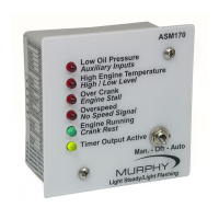
Provides front view mounting dimensions and indicator layout.

Back View Dimensions

Provides back view mounting dimensions and component layout.

Mounting Drill Pattern

Details the required drill hole pattern for panel mounting.

Side View Dimensions

Shows side view dimensions for panel integration.

Mounting the ASM150 Module

Drilling and Insertion

Instructions for drilling holes and inserting the module into the panel.

Label Application

Steps for applying the panel label correctly.

Securing the Module

How to secure the module and label in place with screws.

Wiring the ASM150

Wiring Safety Precautions

Essential safety warnings and guidelines for wiring the ASM150.

Wire Gauge Recommendations

Guidance on wire size for power connections and noise reduction.

Noise Reduction Techniques

Methods to reduce electrical noise, including wire routing and shielded cable.

Load and Output Ratings

Information on output current ratings and protection for inductive loads.

Typical Wiring Diagram

Diagram Notes

Key notes explaining connections and load limits in the wiring diagram.

Making Adjustments to the ASM150

Overspeed Adjustment (R1 Pot)

Procedure for setting the engine overspeed shutdown point.

Crank Disconnect Adjustment (R2 Pot)

Procedure for setting the starter disconnect speed.

Crank/Rest Time Adjustment (R3 Pot)

Setting the duration for engine cranking and resting periods.

Shutdown Lockout Delay (R4 Pot)

Adjusting the delay to ignore start-up sensor signals.

Overcrank Adjustments (DIP Switches)

Configuring the number of cranking attempts using DIP switches.

DIP Switch Setting Chart

Table showing DIP switch settings for crank attempts.

Sequence of Operations

Auto Mode Operation

Describes engine start, running, and shutdown sequences in Auto mode.

Test Mode Operation

Explains how the controller operates when the switch is in Test mode.

Troubleshooting Information

Troubleshooting Symptoms and Actions

Guides users through common symptoms and their corrective actions.

General Troubleshooting Advice

Emphasizes checking wiring and connections before troubleshooting.

Related product manuals