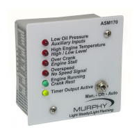
Description
The ASM170 is a state of the art, automatic engine start / stop
controller with selectable warmup / cooldown, glow plug, or choke
capabilities. The ASM170 operates from a 12 or 24 volt battery and can
withstand voltage drops during cranking. It includes crank and rest
cycles, sensing circuit for crank disconnect and overspeed, overcrank,
and recrank protection on false starts. Four red LED’s indicate first out
shutdown from low oil pressure, high temperature, overcrank,
overspeed, auxiliary input, high/low level, engine stall, and no speed
signal. A fifth green LED lights when the engine has started. This same
LED flashes during the rest period while the unit is cycle cranking the
engine. A sixth LED lights when the multifunction output is operating.
This output is programmable using the DIP switches located on the
back of the unit.
The ASM170 is housed in an ABS plastic enclosure and the electronics
are encapsulated in a protective epoxy resin. Due to its low cost and
flexible features, it is ideal for generator or pumping applications.
Specifications
Power Input: 6 to 28 VDC.
Power Consumption Standby (AUTO): <1mA.
Operating Temperature: -40 to 185 °F (-40 to +85 °C).
Inputs: Ground or positive inputs for high temperature, low oil
pressure, High/Low Level, Auxiliary / Remote Stop
sensors. (Note: The momentary start input must be at least 100 ms in
duration to be recognized as a valid start.)
Lamp Test: When unit is powered up in Manual or Auto, the LED’s
light for 1 second as a test.
Outputs: 5A smart FET for cranking and multifunction output.
Sources from battery +. 10A smart FET for Fuel Valve (Energized to
Run) output. Sources from battery +. 125 ma transistor for common
failure, engine run, and auxiliary output. Sinks to battery –.
Crank Attempts: Selectable for 3, 5, 10, or 255.
Crank / Rest Cycle Timing: Field adjustable 1 to 30 seconds.
Multifunction Output: Field programmable to one of the following
options: Glowplug, Cooldown, Warmup/Cooldown, Warmup, Airgate –
Overspeed Only, Airgate – Always, Choke, or Auxiliary Run output.
Shutdown Lockout Time Delay: Field adjustable 1 to 300 seconds.
Locks out low oil pressure, high temperature, and loss of speed
shutdowns on start-up.
Crank Disconnect Speed Setting: From 13 to 2500 Hz.
Overspeed Trip Point Setting: From 13 to 8500 Hz.
Speed Sensing Input: 1.5VAC RMS to 140 VAC RMS.
Shipping Weight: 1 lb. (.45 kg.)
Shipping Dimensions: 6.25 x 6.25 x 4.5 in. (159 x 159 x 114 mm).
Installation Accessories
•
Tools for the module mounting, such as drill and screwdriver.
•
Optional Wire Harness Kit (40000138).
•
12 and 18 AWG (4.2 mm2 and 1.0 mm2) wire for hook up.
•
Set of wire termination tools.
•
Wire Termination; such as spade terminals. 1/4” crimp-on FASTON
®
receptacle.
Mounting Drill Pattern
(Do not scale or use as a template)
Mounting the ASM170 Module
1. To mount the ASM170 module to your panel, drill six (0.25 in.
[6mm] dia.) holes for LED indicators, and two (0.203 in. [5 mm] dia.)
holes for mounting screws. See “Mounting Drill Pattern”, for
dimensions.
2. Insert the ASM170 module from the back of the panel into the pre-
drilled holes.
3. Secure the module in place with the two (2) screws provided.
ASM170 MURPHYMATIC
®
Micro-controller
Installation and Operation Instructions
Please read the following information before installing. A visual inspection of this product for damage
from shipping is recommended before installing. It is your responsibility to have a qualified person install
this unit and make sure it conforms to local codes.
GENERAL INFORMATION
0.750 in. (19 mm)
2.563 in. (65 mm)
2.750 in. (70 mm)
3.100 in. (79 mm)
1.250 in. (32 mm)
1.600 in. (41 mm)
1.950 in. (50 mm)
2.300 in. (58 mm)
2.650 in. (67 mm)
2.750 in. (70 mm)
0.260 in. (7 mm)
0.203 in. (5 mm) dia.
0.203 in.
0.900 in. (23 mm)
0.885 in.