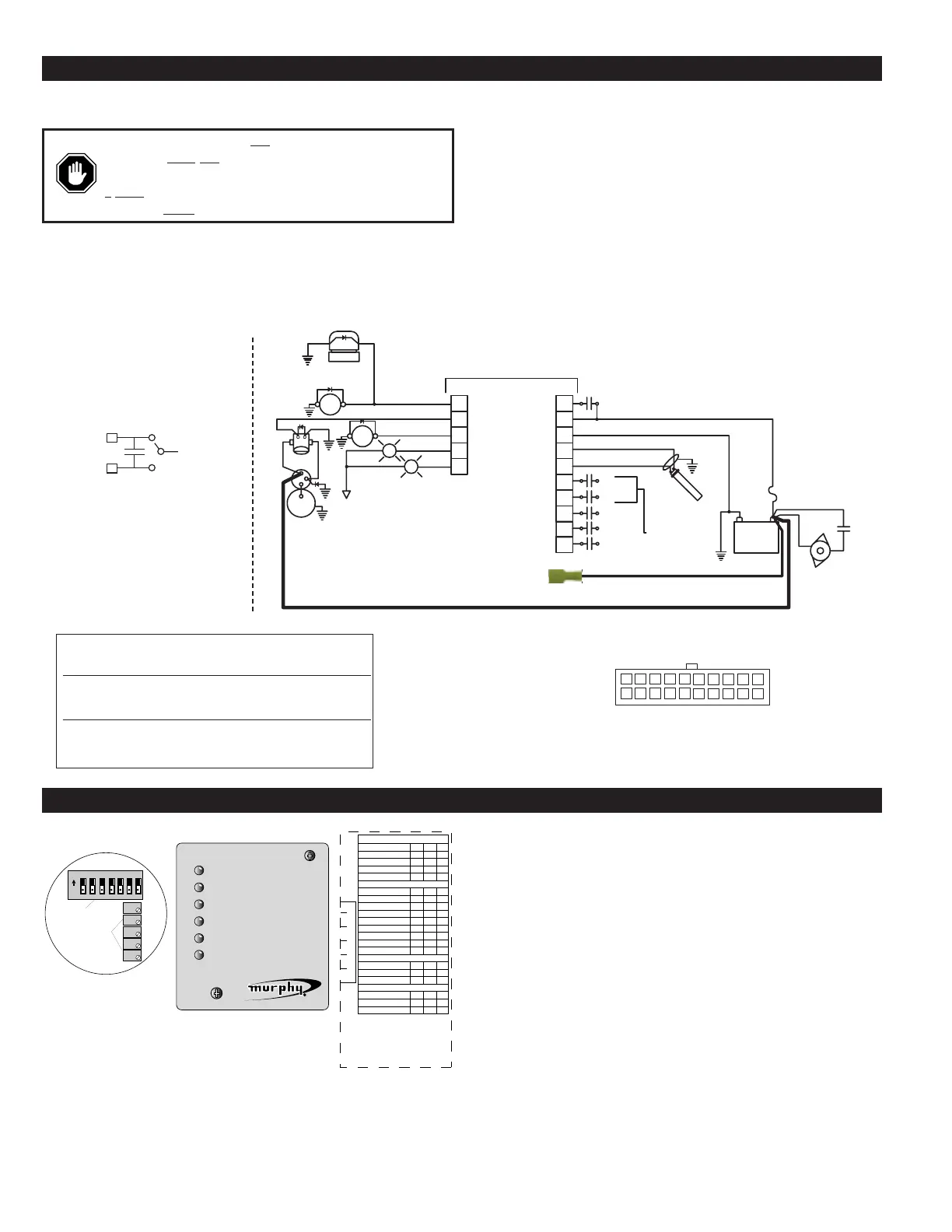
On the back of the ASM170, you will find five (5)
potentiometers and seven (7) DIP switches for
customizing your controller. The five potentiometers
have the following functions:
R1 = Crank / Rest Delay (1-25 seconds)
R2 = Overspeed Frequency (13-8500 Hz)
R3 = Crank Disconnect Frequency (13-2500 Hz)
R4 = Multifunction Timer.
R5 = Lockout Delay (1-300 seconds)
Crank / Rest Delay (R1 Pot) – Adjustable between 1 and 25 seconds
The Crank / Rest adjustment is used to vary the amount of time the
cranking output is ON and OFF during the start sequence. When a start
attempt begins, the controller will energize the cranking output for the
amount of time set on this pot. If the engine is not sensed to have started,
the controller will de-energize the cranking output for the same period of
time before energizing it again. During the rest period the RUN light
will flash.
Overspeed (R2 Pot) – Adjustable between 13 and 8500 Hz
The OVERSPEED adjustment is used to set the point at which the unit
will signal for a shutdown if the engine speed should reach too high an
RPM. To set the OVERSPEED value, turn the OVERSPEED Pot fully
clockwise and run the engine up to the maximum operating speed. Next,
slowly turn the Pot counterclockwise until the engine shuts down on
OVERSPEED. Now, turn the Pot clockwise two turns. This will adjust
the OVERSPEED set point approximately 8% higher than the maximum
engine operating speed.
Crank Disconnect (R3 Pot) – Adjustable between 13 and 2500 Hz
The CRANK DISCONNECT adjustment is used to let the ASM170
know when the engine has started so that it will turn OFF the cranking
output. Turn R3 clockwise 25 turns, and then turn R3 counter clockwise
The ASM170 is a pilot duty device. The outputs are designed for
control only.
1. Wire the ASM170 using 18 AWG stranded wire. When wiring to the
push on FET common terminal, we suggest using a larger wire size (12
AWG recommended).
2. When hooking the battery positive (+) and ground wires to the
ASM170, route them directly from the battery to the unit. This will help
reduce electrical noise coupling and avoid voltage losses from other
devices.
3. If a standby battery charger is installed, it must be wired directly to the
battery, NOT to the ASM170. This could cause electronic “noise”
produced by the charger to be coupled into the microprocessor. If the
“noise” is severe, erratic operation could occur.
4. Do not route low voltage DC (battery) control wires in the same conduit
as high voltage AC wires.
5. Use shielded cable for connecting the magnetic pick up to the ASM170.
Ground only one end of the shield (we suggest you ground it at the
engine).
6. Always place reverse bias diodes across inductive loads. This helps
eliminate a source of electromagnetic noise.
WIRING THE ASM170
WARNING:
Disconnect ALL electrical power before beginning
the wiring. STOP
ALL machinery before performing the hook up.
Any load connected to the panel which draws current in excess of
5
Amps for the crank and multifunction outputs or 10 Amps for the
fuel output MUST
be piloted at the load.
ASM-03024N page 2 of 4
MAKING ADJUSTMENTS TO THE ASM170
Freq. (-)
(Mom. Stop)
Ex.
Aux. 2
Aux. Inputs
 Loading...