Warranty
A limited warranty on materials and workmanship is given with this FWMurphy product.
A copy of the warranty may be viewed or printed by going to www.fwmurphy.com/warranty.asp.
SEQUENCE OF OPERATIONS
ASM-03024N page 4 of 4
Sequence of Operation with Panel in “AUTO”
The ASM170 module is very flexible. The basic sequence of operation follows:
When a start signal is received, the following occurs:
•
The frequency is checked relative to the crank disconnect set point. If the
frequency is sensed to be above the set point, the fuel valve will turn on and
the engine run light will light. The following delays will also begin timing:
• Shutdown Lockout Delay
• Warmup Delay (If selected)
•
If the frequency is sensed to be below the set point the fuel valve will turn on,
the multifunction output will turn on (if required – see MULTIFUNCTION
OUTPUT OPTIONS section) and cycle cranking will begin.
• During Cycle cranking, the Fuel Valve output is on continuously.
• If the Multifunction output is set to glowplug, the unit will first turn on the
output for the selected amount of time, turn it off then energize the start
output. If the unit does not start, the start output will be de-energized
through the rest delay and the run light will flash. When the rest delay
expires, the multifunction output will then be energized through the delay,
turn off, and the start output will be energized again. This sequence will
continue until the engine is sensed to start or OVERCRANK occurs.
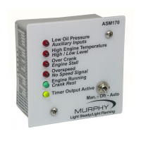
• If the engine starts but then stalls, the ENGINE STALL LED will flash for
10 seconds. After the 10-second delay expires, the cycle cranking sequence
will continue. These “Engine Stalls” or “False Starts” are counted as crank
attempts.
• OVERCRANK – If the engine fails to start within the selected number of
crank attempts, the fuel output will be de-energized, the common fail
output will be energized and the OVERCRANK LED will light. Before the
module will attempt to start the engine again, this shutdown condition must
be reset by moving the selector switch to the OFF position and back to
AUTO.
• If the unit successfully starts the engine by cycle cranking, the starter
output will immediately be deenergized, the ENGINE RUNNING light will
turn on and the multifunction output will perform any necessary functions
(see MULTIFUNCTION OUTPUT OPTIONS section). The following
delays will begin timing:
• Shutdown Lockout Delay
• Warmup Delay (If selected)
• The following shutdown conditions are armed immediately:
• OVERSPEED
• LOW LEVEL
• Once the Shutdown lockout delay has timed out, the unit will arm the
following shutdowns:
• LOW OIL PRESSURE
• HIGH ENGINE TEMPERATURE
• AUXILIARY INPUT ONE
• NO SPEED SIGNAL
• When the start signal is removed or the stop signal is sensed the unit will
shutdown the engine. If the multifunction output is required to function at this
time it will (see MULTIFUNCTION OUTPUT OPTIONS section). When it is
ready for shutdown the fuel valve will be de-energized and the controller will
await another start signal.
SHUTDOWNS: If the controller senses any shutdown conditions while it is
running, the fuel output will be de-energized, the common fail output will be
energized and the appropriate shutdown LED will light. Before the module will
attempt to start the engine again, the unit must be reset by moving the selector
switch to the OFF position and back to the AUTO position.
Sequence of Operation with Panel in “MANUAL”
When the MANUAL-OFF-AUTO switch is placed in the “MANUAL” position,
an automatic start signal is simulated. Therefore, the controller will operate the
same as it does in “AUTO.” However, it will continue to run as long as there are
no signals from monitored conditions or until the MANUAL-OFF-AUTO switch
is moved to the “AUTO” or “OFF” positions. There is no cooldown or airgate
feature available in the manual mode. Keep in mind; it will still shut down the
engine if a monitored condition occurs such as low oil pressure or high
temperature.
ASM170 I/O List
noitamrofnI lanoitiddAemaN erawdraHlebaL#NIP
1 rotareneG ro pukciP citengaM nruteR hcaT-ycneuqerF
2 suniM yrettaB-B)-B( dnuorG
3 Start (Manual) Input 1 Battery Plus Only
4 )tuO dekcoL toN–detavitca nehw no snruT tuptuO liaF nommoC ylnO( tupnI -/+6 tupnI1 tupnI xuA
5 mralA teseR otuA ro nwodtuhS 6WS tupnI -/+5 tupnIleveL
6 High Temperature Input 3 +/- Input
7 Engine Run Out Output 5 125 mA Sinking
8 dnuorg ot sknis nip siht ,evitca si 6 tupnI nehW-gnikniSAm 5216 tuptuOdesU toN
9 pukooH oNrewoPTEFenoN
pukooH oNrewoPTEFenoN01
11 rotareneG ro pukciP citengaMhcaT+ ycneuqerF
AOM fo noitisoP otuA)+( yrettaBotuA21
13 Low Oil Pressure Input 2 +/- Input
14 Aux Input 1/Remote Stop Input 4 +/- Input
15 Multifunction Output Output 3 5 AMP FET
16 Common Shutdown Output Output 4 125 mA Sinking
17 Crank Output Output 1 5 AMP FET
TEFPMA 012 tuptuOtuptuO leuF81
pukooH oNrewoPTEFenoN 91
pukooH oNrewoPTEFenoN02
Blade FET Common FET Power Push On for FET Supply Power (20 AMPS)

 Loading...