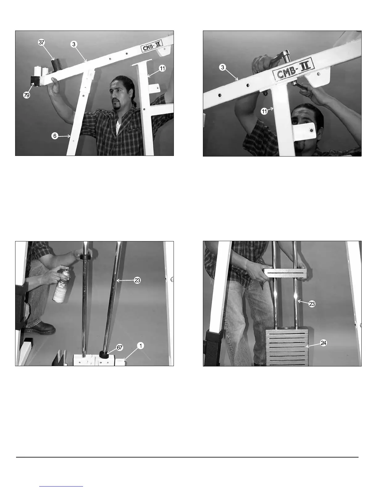
FIG. 9 Attach the Top Pulley Assembly (#3) onto the Rear
Upright (#6), as shown above, and secure using one Hex
Head Cap Screw 3/8-16 X 2 3/4 (#55), two Flat Washers SAE
3/8 (#73) and one Nylon Insert Jam Lock Nut 3/8-16 (#69).
Next, insert two Plastic Insert Caps 2” Sq. (#79) into the tube-
ends of the Top Pulley Assembly (#3), as shown above.
Next, attach a Rubber Stopper 1 X 2 X 2 1/2 (#37) to the prong
on the Top Pulley Assembly (#3), as shown above.
FIG. 10 Secure the Top Pulley Assembly (#3) to the Front
Upright (#11) using two Hex Head Cap Screws 3/8-16 X 3
(#61), four Flat Washers SAE 3/8 (#73) and two Nylon Insert
Lock Nuts 3/8-16 (#70).
FIG. 11 Insert the two Guide Rods (#23) into the receptacle
of the Base Frame (#1), as shown above. Next, insert two
Rubber Donuts 1 X 2 1/2 (#67) onto each Guide Rod (#23).
Note: Lubricate the Guide Rods (#23) with a silicone or Teflon
lubricant at this time.
FIG. 12 Carefully begin sliding the 10 Lb Weight Plates
(#24) over the Guide Rods (#23), one or two at a time as your
skill permits. Make sure that the 10 Lb Weight Plates (#24) are
installed onto the Guide Rods (#23) in numerical order,
beginning with the number 200 at the bottom, 190 next, and so
on.
Owners’ Manual: Assembly Instructions
CMB-2 Muscle Beach Home Gym
4


 To Next Page
 Loading...
