The camera will then take a photo of this pattern and the display will show the plotted image with a
small red cross and long dotted blue lines superimposed.
Tap the middle of the pattern with your nger to move the small red cross close to the center. You can
use the arrow keys, if you like, to place it more precisely in the middle. The x3 button on the control
panel enables magnifying the camera view for extremely precise alignment.
The Muse will take over and locate the center precisely. You will then conclude the calibration by
pressing STOP on the MAIN SCREEN.
Step-by-Step Calibration Process
3.1.1
The following steps show you how to create your own preset of cut settings:
1.
2.
3.
4.
5.
6.
7.
8.
9.
Load the sheet of paper into the cutter, taking care to adjust the position of the pinch rollers so that the
paper is securely placed on the platen.
The recommended SPEED and FORCE settings for the camera calibration are 8 and 30, respectively. This
will help the pen draw a clear and clean test pattern for the calibration.
Place the test pen into the tool carriage. You can open the lid to gain more room to insert the test pen.
Make sure you position the pen in the blade holder seat so that it’s low enough to mark the paper when
lowered, but high enough to clear the paper when the blade holder seat is raised. Use the TEST button to
draw a test square to make sure the pen is positioned correctly.
Once your small test square is cleanly drawn, move the pen over so that the calibration pattern will not be
drawn on top of your last test.
From the main screen, press SET>CAMERA.
Press START. The test shape, which is a grid of 6
lines, will be drawn on the paper and the camera
will move over the test shape, take a photo, and
display the photo on the control panel.
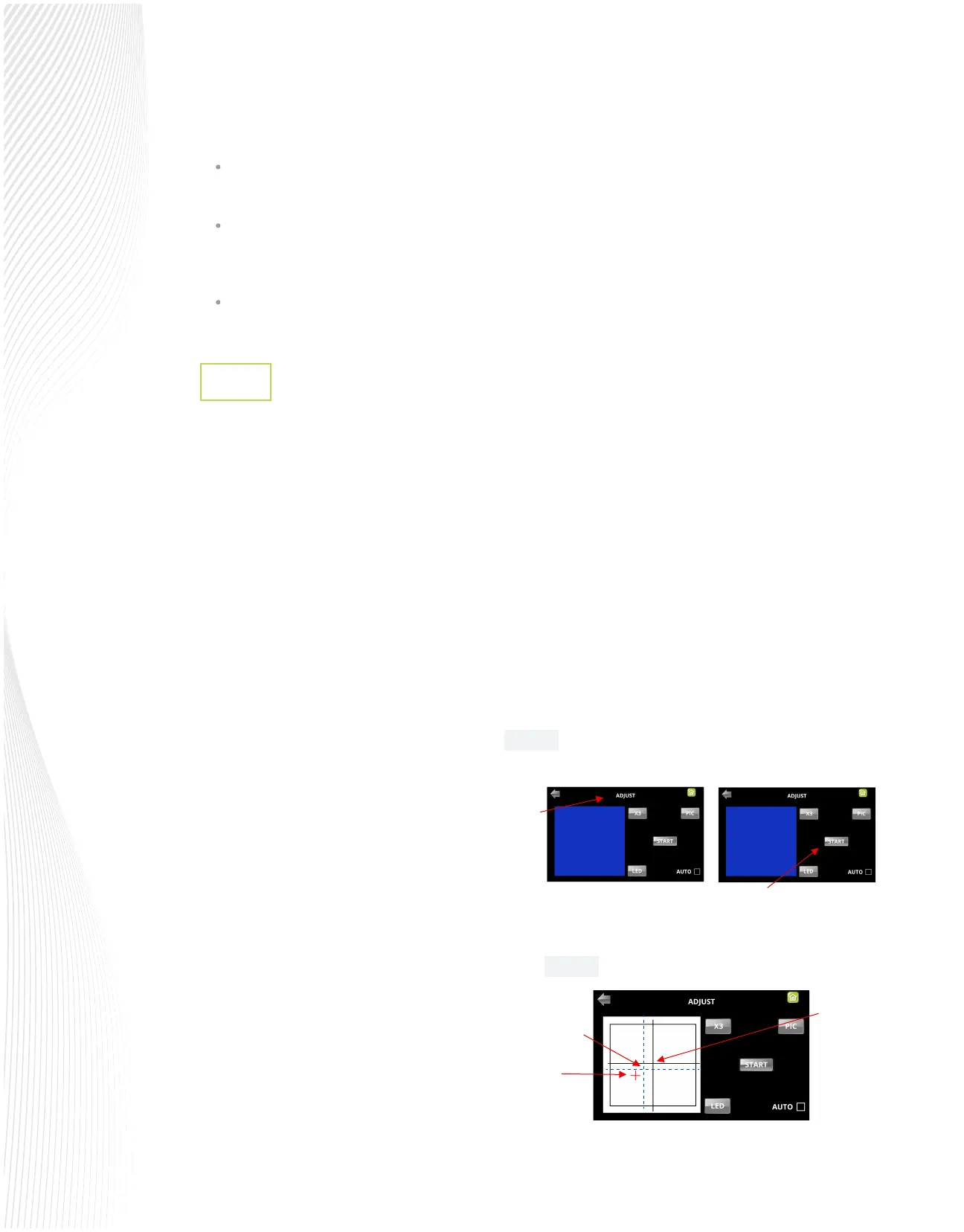
If you cannot see the test shape clearly, press the
LED button once so that it reads LED 50%. You can
also use the X3 button to zoom in, if needed. Press
the PIC button to take another photo. You should
see three items in the photo: the test shape that
was drawn with the pen, a red +, and the blue
dashed +:
Select ADJUST to open the screen for calibrating.
Press START:
Press and hold the OK button for several seconds
Fig. 3.1.2
Fig. 3.1.1
Red +
Blue dashed +
Tap your
nger here
Select
Adjust
Press and hold OK
Press Start
 Loading...