9.-ON:ThisLEDindicatesthattheprocessorisinworkingcondition.
10.-POWER:Mainsswitchoftheprocessor.
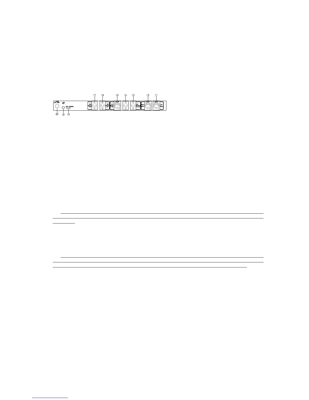
On the rearoftheprocessor you will find the socketsforthesignals
andpowercontrolconnectors,aswellasthemainspowersupplysocketfor
thisunit.
11. - LEFT INPUT: Signal input for the left channel. This requires an
XLR-typeconnector.
This socket is connected directly to the left channel input socket on the
rearrackpanel.
12 - RIGHT INPUT: Signal input for the right channel. This requires an
XLR-typeconnector.
Thissocketisconnecteddirectlytotherightchannelinputsocketonthe
rearrackpanel
13-14.-LOWOUTPUTS(LINKED):Signaloutputforthebassway.Thisisa
monauraloutput,resultingfromthesumofbothsignalsofthesubbassways
ofbothchannels.
IMPORTANT!Iftheconnectionofeitherchannelshouldfailornotbein
perfectworkingcondition,theoutputlevelofthesubbasswoulddecrease
by3dB.
15.-LOWSENSEINPUT:SENSEinputforthesubbassway.Thislinecomes
directly from the male XLR connector of the power amplifier output.
Information about the power is constantly sent here from the amplifier to
theprocessor.
ATTENTION! If this SENSE line is disconnected or damaged, the power
controlcircuitswillnotwork,resultingindamagedsubbassloudspeakers.
Insuchcase,theguaranteewillnotcovertherepairofthespeakers.
16.-HIGHOUTPUTLEFT:Thisisthehigh-passfiltersignaloutputofthe
left channel. This output is to be connected directly to the rack’s rear
panelconnectornamed"OUTPUTS-LEFTCHANNEL".
17-HIGHOUTPUTRIGHT:Thisisthehigh-passfiltersignaloutputofthe
right channel. This outputisto be connecteddirectly to the rack’s rear
panelconnectornamed"OUTPUTS-RIGHTCHANNEL".
18. -FLOAT-GROUND: Chassis ground switch. In the FLOAT position the
chassisiselectricallyinsulatedfromthecircuit’sground(mass).Inthe
GROUNDpositionbothgroundsareconnected.
Changing the switch’s position can eliminate buzzing sound generated by
groundfeedback.
 Loading...