Do you have a question about the Must HBP1800 and is the answer not in the manual?
Read all instructions, avoid disassembly, ensure proper grounding, and follow operational safety guidelines.
Check the equipment before installation to ensure no damage occurred during transit.
Ensure proper clearance for heat dissipation and connect power sources before turning on the device.
Choose a suitable, sturdy location with proper ventilation and clearance for installation.
Choose PV modules considering open-circuit voltage, optimal working voltage, and system battery voltage.
Turn the unit on or off by simply pressing the on/off button located on the chassis.
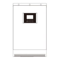
Overview of the front panel including LCD display, indicator lights, and function keys for operation.
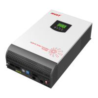
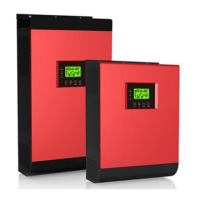
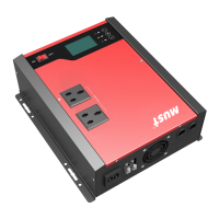
This document outlines the assembly, installation, operation, and troubleshooting of a multi-functional photovoltaic energy storage power station. It is designed for outdoor backup electric compartments and spontaneous self-use systems. The device integrates a battery, an MPPT solar charge controller, a high-frequency pure sine wave inverter, and a UPS function module.
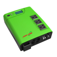
The core function of this device is to provide a portable photovoltaic energy storage solution. It acts as a power station that can store energy from solar panels and supply AC power to various appliances. The MPPT solar charge controller utilizes an advanced MPPT method and intelligent battery management to maximize energy acquisition from solar panels. The high-frequency pure sine wave inverter ensures a high rate density, compact size, and simple operation, with minimal load loss. The device supports both AC and PV inputs, allowing for flexible power sourcing and charging options. It also features 5V USB and 12V DC outputs for charging smaller devices.
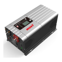
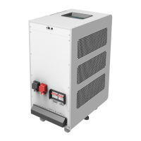
The system is designed with a pure sine wave AC output inverter, available in 1KW, 2KW, and 3KW rated power with a power factor of 1. It boasts high power density and universal wheels for enhanced portability. Users can configure input voltage and voltage ranges via the LCD screen. The device offers configurable AC/PV input and battery priority levels, allowing users to optimize power usage based on their needs. Comprehensive protection functions are integrated, including safeguards against overload, over-temperature, and short circuits, ensuring safe and reliable operation.
The device's operational states include Utility-Tie state (PV energy charges the battery, and utility power supplies the AC load), Charge state (PV energy and grid can charge batteries), Bypass state (triggered by internal circuit errors or external reasons like over-temperature or short circuits), Off-Grid state (inverter supplies power from battery and PV), and Stop mode (inverter stops working due to soft key turn-off or error in no-grid conditions).
The device is designed for ease of use and flexibility. Once installed and connected to batteries, it can be turned on by simply pressing the on/off button located on the chassis. The front panel features an LCD display, three indicator lights, and four function keys for operation and monitoring. The LCD provides real-time information on running status, input, and output.
The LED indicators offer quick visual cues:
The function keys allow for various settings and navigation:
The LCD display icons provide detailed information:
Users can enter setting mode by pressing and holding the "ENTER" button for 2 seconds, then use "UP" or "DOWN" to select programs and "ENTER" or "MENU" to confirm. Settings include output source priority (solar energy or utility priority), AC input voltage range (Appliances, UPS, VDE, Generator mode), output voltage amplitude, output frequency, solar supply priority, overload bypass, auto restart for overload/over-temperature, charger source priority (solar first or solar and utility), maximum charging current, maximum utility charging current, bulk charging voltage, floating charging voltage, low DC cut-off battery voltage, battery stop discharging/charging voltage when grid is available, auto turn page, backlight control, alarm control, beeps for primary source interruption, record fault code, solar power balance, power saving mode, battery equalization settings (enable/disable, voltage, time, timeout, interval), and immediate equalization activation.
The manual emphasizes several safety and maintenance guidelines to ensure the longevity and proper functioning of the device. Before installation, users are instructed to check the package for any damage and confirm all included items are present. Proper preparation involves reserving adequate space (at least 30CM above and 200mm to the sides) around the device for heat dissipation. All connections, especially the grid and AC input, must be firmly secured, and the machine should not be moved during operation.
Installation should be on a sturdy, non-flammable surface, at eye level for easy LCD reading. The ambient temperature should be between 0-50 °C for optimal performance. The manual strongly advises against disassembling the unit; any service or repair should be performed by a professional service center to prevent electric shock or fire. Before any maintenance or cleaning, all wiring must be disconnected.
The warranty does not cover issues arising from an overdue warranty period, altered or lost serial numbers, low battery capacity, damaged appearance, external factors (transportation, negligence), natural disasters, or damage due to non-compliance with power supply conditions or operating environment.
The device also includes fault reference codes and warning indicators displayed on the LCD, which are crucial for troubleshooting. Fault codes (e.g., Fan locked, Inverter transformer over temperature, Battery voltage too high/low, Output short circuited) and warning indicators (e.g., Fan locked when inverter is on, Battery over-charged, Low battery, Overload, Output power derating) help users identify and address issues promptly. The ability to record fault codes (program 27) aids in diagnostics.
Battery equalization settings (programs 30-36) allow for proper battery maintenance, extending battery life. Users can set equalization voltage, time, timeout, and interval, or activate it immediately. The power saving mode (program 29) helps conserve energy by turning off the inverter output when the connected load is very low or not detected.
| Output Voltage | 230 VAC |
|---|---|
| Waveform | Pure sine wave |
| Model | HBP1800 |
| Input Voltage | 230 VAC |
| Input Frequency Range | 50 Hz / 60 Hz (Auto sensing) |
| Transfer Time | ≤10ms |
| Frequency | 50 Hz / 60 Hz (Auto sensing) |
| Protection Features | Overload, over temperature, and short circuit protection |
| Cooling | Fan |