EasyManua.ls Logo

Mutable Instruments Braids User Manual

Mutable Instruments Braids
8 pages
To Next Page IconTo Next Page
Page #1 background image
Braids user manual
Note: this user manual documents the version 1.5 of the firmware. If another version is
installed, please upgrade! You can find out which version is installed by clicking on the
encoder and scrolling to the end of the menu.
Overview
Mutable Instruments’ Braids is a voltage-controlled digital sound source. It features 33
waveform synthesis models, which cover techniques such as FM, wavetable synthesis,
waveguide synthesis or analog emulation. Most synthesis models are built with one or
several oscillators connected through crossfaders, modulators, filters, or delay lines. Each
synthesis model is controlled by 2 parameters, called Timbre and Color.
Installation
Mutable Instruments’ Braids is designed for Eurorack synthesizer systems and occupies 16
HP of space. It requires a -12V / +12V / +5V supply (2×8 connector), consuming 15mA from
the -12V / +12V rails and 85mA from the +5V rail. The red stripe of the ribbon cable must be
oriented on the same side as the “Red stripe” marking on the printed circuit board.
Controls
A: LED display and rotary encoder. When the module
starts, the LED display shows the name of the active
synthesis model, and the encoder can be used to select a
model. Click the encoder to display a list of additional
settings and options. Click the encoder to select an option
and modify its value. Once the value has been modified to
your liking, click the encoder to get back to the list of
options. Selecting the first option (“WAVE”), saves to
memory the current setup and brings you back in model
selection mode.
B, C: Fine and coarse frequency control.
D: Frequency modulation attenuverter. This knob controls
the amount and polarity of modulation applied to frequency,
from the FM CV input jack.
E: Timbre. This parameter controls the main evolution and
motion of the timbre – for example pulse width for a square
oscillator or modulation index for a FM model.
F: Modulation attenuverter. This knob controls the amount
and polarity of modulation applied to the TIMBRE
parameter, from the TIMBRE CV input jack.
G: Color. This knob controls a second dimension of sound, for example the symmetry of an
oscillator or the modulation frequency for a FM model.

Other manuals for Mutable Instruments Braids

Question and Answer IconNeed help?

Do you have a question about the Mutable Instruments Braids and is the answer not in the manual?

Mutable Instruments Braids Specifications

General IconGeneral
BrandMutable Instruments
ModelBraids
CategoryMusic Equipment
LanguageEnglish

Summary

Overview and Installation

Braids Controls

LED Display and Rotary Encoder

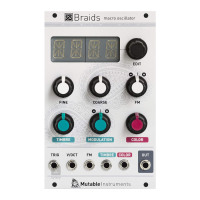
Controls module display, selection of synthesis models, and access to settings.

Fine and Coarse Frequency Control

Knobs B and C adjust the primary pitch of the oscillator.

Frequency Modulation Attenuverter

Knob D controls the amount and polarity of FM CV input.

Timbre Parameter Control

Knob E adjusts the main evolution and motion of the timbre.

Timbre Modulation Attenuverter

Knob F controls the amount and polarity of TIMBRE CV input.

Color Parameter Control

Knob G controls a second dimension of sound, like symmetry or modulation frequency.

Inputs and Outputs

Trigger Input (TRIG)

Serves three purposes: sound excitation, oscillator reset, or internal AD envelope trigger.

1V/Oct Frequency CV Input

Controls the oscillator frequency with 1V/Oct standard.

Frequency Modulation CV Input (FM)

Input for frequency modulation, scaled by the FM attenuverter.

Timbre and Color CV Inputs

Control voltages for the Timbre and Color parameters.

Signal Output (OUT)

The main audio signal output.

Synthesis Models

CSAW Model

Inspired by Yamaha CS80 sawtooth wave with a fixed-width notch.

M/-/- Waveform Trajectory

Morphs from triangle to sawtooth to square to pulse waveforms.

-/-/- Dephasing Sawtooth

Blends dephased sawtooth with a PWM square wave.

SYNC Hardsync Patch

Synthesizes classic 2-oscillator hardsync patch with square waves.

FOLD Wavefolder

Uses sine and triangle oscillators sent into a wavefolder.

Sine to Dirac Comb

Generates a smooth waveform sequence from sine to Dirac comb.

Three Individually Tuned Oscillators

Three sawtooth or square oscillators with individually tuned frequencies.

RING Modulated Sine Waves

Three sine wave oscillators ring-modulated together.

Swarm of Sawtooth Waves

Simulates a swarm of 7 sawtooth waves with detuning.

Comb Filtered Sawtooth

Generates a sawtooth waveform into a comb filter (tuned delay line).

TOY* Electronic Toy Emulation

Traverses timbres typical of circuit-bent electronic musical toys.

Time-Domain Filter Synthesis

Synthesizes filter responses like low-pass, band-pass, directly in time-domain.

VOSM Formant Synthesis

Emulates formant synthesis using ring-modulation/hardsync patch.

VOWL and VFOF Vowel Sounds

Synthesizes vowel sounds, recreating early computer speech synthesis.

FM, FBFM, WTFM Phase Modulation

Three flavors of 2-operator phase-modulation synthesis.

BELL Additive Synthesis

Uses additive synthesis to recreate the tone of a bell.

DRUM Metallic Drum Emulation

Variant of BELL model for metallic drum sounds.

PLUK Raw Plucked String

Raw plucked string synthesis.

BOWD Bowed String Modeling

Bowed string modeling.

BLOW and FLUTE Instrument Models

Reed or flute instrument models.

WTBL Wavetable Synthesis

Classic implementation of wavetable synthesis.

WMAP 2D Wavetable Synthesis

Two-dimensional implementation of wavetable synthesis.

WLIN 1D Wavetable Scanning

One-dimensional scanning through wavetables.

WTx4 4-Voice Wavetable

A 4-voice variant of WLIN with different harmonic structures.

NOIS Filtered White Noise

Filters white noise with a state-variable filter.

TWNQ Twin Peaks Noise

Generates white noise processed with two band-pass filters.

CLKN Random Sample Generator

Generates random samples at a given rate.

CLOU and PRTC Granular Synthesis

Granular synthesis models using sine waves or decaying pings.

QPSK Digital Telecommunication Signals

Generates modulated signals used in digital telecommunication.

Module Options

BITS DAC Bit-Depth

Selects the bit-depth of the data sent to the DAC.

RATE DAC Refresh Rate

Selects the refresh rate of the DAC.

TSRC Trigger Source Selection

Selects the trigger source (external or automatic).

DLY Trigger Delay

Applies a delay between trigger reception and note strike.

TDST Trigger Input Action

Defines action upon trigger input: SYNC, TIMB, LEVL, or BOTH.

TENV Internal Envelope Shape

Selects a preset shape for the internal AD envelope.

META CV Model Selection

Allows synthesis model selection via FM CV input.

RANG Coarse Knob Range

Chooses the range for the coarse frequency knob.

OCTV Octave Transposition

Switch for octave transposition.

QNTZ V/Oct Signal Quantization

Quantifies the incoming V/Oct signal to semitones or quarter tones.

FLAT Frequency Detuning

Applies detuning in lower and higher frequencies.

DRFT VCO Imperfection Emulation

Recreates VCO imperfections from power supply and noise.

SIGN Glitches and Imperfections

Applies glitches/waveform imperfections to the output signal.

BRIG Screen Brightness

Adjusts the screen brightness.

Calibration and Utilities

Module Calibration Procedure

Procedure to scale input control voltages for accurate operation.

Toy Mode: ADC Visualisation

Visual representation of internal ADC readings for inputs.

Toy Mode: Text Editing

Allows editing of text strings using the encoder.

Firmware Update and Warranty

Firmware Update Procedure

Step-by-step guide for updating the module's firmware.

Product Warranty Information

Details Mutable Instruments' warranty terms and conditions.

Related product manuals