EasyManua.ls Logo

Mutable Instruments Plaits User Manual

Mutable Instruments Plaits
11 pages
To Next Page IconTo Next Page
Page #1 background imageLoading...
Page #1 background image
Plaits requires a -12V/+12V power supply (2x5 pin connector). The red stripe of the ribbon cable (-12V
side) must be oriented on the same side as the Red stripe marking on the module and on your power
distribution board. The module draws 50mA from the +12V rail, and 5mA from the -12V rail.
This device complies with part 15 of the FCC Rules. Operation is subject to the following
two conditions: (1) This device may not cause harmful interference, and (2) this device must
accept any interference received, including interference that may cause undesired
operation.
This device meets the requirements of the following standards: EN55032, EN55103-2,
EN61000-3-2, EN61000-3-3, EN62311.
A. Model selection buttons and LEDs displaying the active model. Each button cycles through a bank of
8 models. The second bank is focused on noisy and percussive sounds.
Mutable Instruments | Plaits
1 of 11
Question and Answer IconNeed help?

Do you have a question about the Mutable Instruments Plaits and is the answer not in the manual?

Mutable Instruments Plaits Specifications

General IconGeneral
PolyphonyMonophonic
Synthesis MethodsFM, Granular, Wavetable, Noise
OutputsAudio output
Dimensions12HP
Gate Inputs1x Trigger Input
ControlsMorph

Summary

INSTALLATION AND HARDWARE

Power Supply and Connection

Plaits requires a -12V/+12V power supply with specific ribbon cable orientation.

FRONT PANEL OVERVIEW

Control Layout Identification

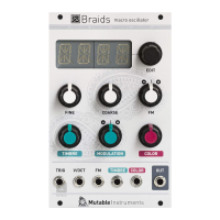
Identifies front panel controls including buttons, knobs, and input/output jacks.

CONTROL DESCRIPTIONS

Model Selection and Tone Controls

Buttons and LEDs for model selection, and controls for spectral content, timbre, and harmonics.

Attenuverter Functionality

Attenuverters for CV inputs allowing modulation depth control and internal envelope fallback.

INPUTS AND OUTPUTS

CV and Trigger Inputs

Inputs for model selection, parameter modulation, and triggering functions.

SETTINGS AND CONFIGURATION

LPG and Envelope Adjustments

Adjusting LPG response and envelope decay times via specific knob combinations.

Frequency Knob Range Adjustment

Hold button A and turn HARMONICS knob to set the FREQUENCY knob's octave range.

SYNTHESIS MODELS OVERVIEW

Related product manuals