EasyManua.ls Logo

Mutable Instruments Tides User Manual

Mutable Instruments Tides
5 pages
To Next Page IconTo Next Page
Page #1 background imageLoading...
Page #1 background image
5/3/2018 Mutable Instruments | Tides
https://mutable-instruments.net/modules/tides/manual/ 1/5
Tides
User manual
OVERVIEW
Tides is a digital waveform generator providing both single-shot and cyclic operation modes, and covering
a very wide range of frequencies from 0.5mHz to 10kHz. As such, it can serve as an AD or AR envelope
generator, a LFO, or an audio oscillator. Its unique design allows the waveform to be controlled along 3
dimensions: curvature of the rise and fall segments (shape), relative timing of the rise and fall segments
(slope), and harmonic content (smoothness).
INSTALLATION
Tides is designed for Eurorack synthesizer systems and occupies 14 HP of space. It requires a -12V /
+12V supply (2x5 connector), drawing 5mA from the -12V rail and 55mA from the +12V rail. The red stripe
of the ribbon cable must be oriented on the same side as the “Red stripe” marking on the printed circuit
board.
This device complies with part 15 of the FCC Rules. Operation is subject to the following
two conditions: (1) This device may not cause harmful interference, and (2) this device must
accept any interference received, including interference that may cause undesired
operation.
This device meets the requirements of the following standards: EN55032, EN55103-2,
EN61000-3-2, EN61000-3-3, EN62311.
CONTROLS, INPUTS AND OUTPUTS

Other manuals for Mutable Instruments Tides

Question and Answer IconNeed help?

Do you have a question about the Mutable Instruments Tides and is the answer not in the manual?

Mutable Instruments Tides Specifications

General IconGeneral
BrandMutable Instruments
ModelTides
CategoryModulator
LanguageEnglish

Summary

Mutable Instruments Tides Overview

Tides Installation and Power

Eurorack System Requirements

Details 14 HP space, -12V/+12V supply, and current draw for Tides installation.

Controls, Inputs, and Outputs Explained

Module Controls

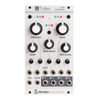
Explains the function of switches (A, B) and knobs (C, D, E, F, G) for Tides operation.

Module Connections

Describes all inputs (1-9) and outputs (10-13) for patching and signal routing.

Tides Clocked and PLL Mode

Frequency Synchronization Ratios

Lists available clock division and multiplication ratios for synchronized operation.

Time Domain vs Frequency Domain Perception

Tides Calibration Procedures

CV Input Calibration

Calibrates V/Oct, FM, and Level inputs for accurate voltage tracking and offset.

Bipolar Output Offset Calibration

Adjusts the bipolar output trimmer to ensure it reads 0V when no signal is present.

Firmware Update Procedure

Mutable Instruments Tides Warranty