REF10
NANO
10
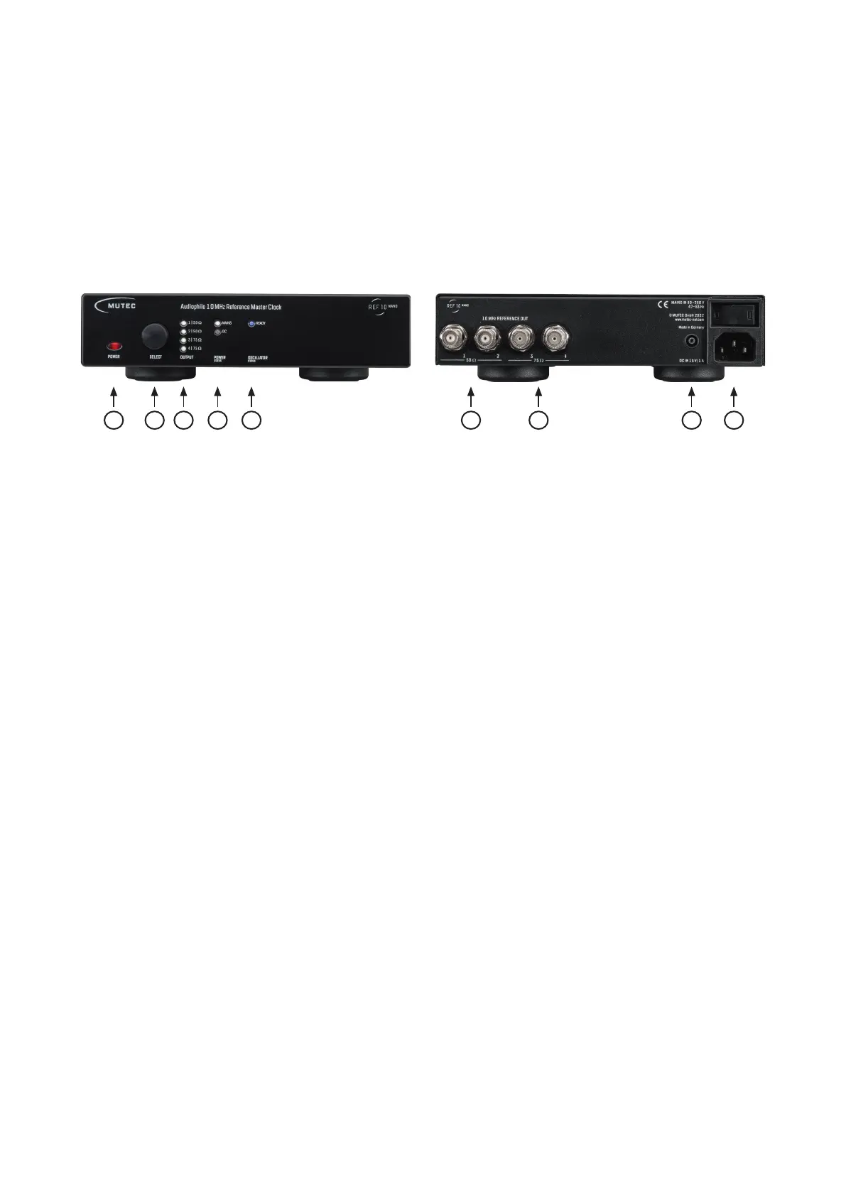
Control Elements and Terminals
Front Panel
1) »POWER«
This red LED illuminates when the device has been powered
up. First engage the rear panel power switch next to the mains
terminal.
2) »SELECT«
This combined push button rotary encoder is used to select
the individual outputs and to disengage or re-engage them.
3) »OUTPUT«
These four white LEDs represent the four rear panel clock out-
puts and reflect if the respective output has been turned on
or off. An illuminated LED means the output is active, i.e on.
4) »POWER«
These two white LEDs indicate which of the two possible po-
wer sources is active. The REF10 NANO can be powered by
mains or DC power.
5) »OSCILLATOR«
This blue LED reflects the status of the oscillator heat-up pro-
cess. Upon powering the device up this LED will be flashing
until the oscillator has reached its correct operating tempera-
ture. Once the temperature has been established, the LED will
be permanently lit.
Rear Panel
1) »50 , Outputs 1– 2«
These two clock outputs are equipped with a 50 Ω terminati-
on. Use only BNC cables with the appropriate 50 Ω impedan-
ce with these outputs.
We recommend using the MUTEC PSC 50 BNC cable.
2) »75 , Outputs 3 – 4«
These two clock outputs are equipped with a 75 Ω terminati-
on. Use only BNC cables with the appropriate 75 Ω impedan-
ce with these outputs.
We recommend using the MUTEC PSC 75 BNC cable.
3) »DC IN 15 V
|
1 A«
This is the DC power input connector accepting 15 V DC po-
wer. When a working DC power source is connected to this
input, the internal self-switching power supply automatically
turns off ensuring the exclusive DC power supply of the REF10
NANO. A matching DC power cable connector is included in
the scope of delivery.
4) »MAINS IN«, Power Switch + Mains connector (IEC)
This is the main switch for switching the device on and off.
Connect the supplied IEC power cable to the device‘s mains
connector. Make sure the power switch is turned off before
connecting the device to your power source finally. Line vol-
tages within the range of 90…260 V with a frequency of 50
or 60 Hz can be applied. The internal power supply will auto-
matically make all necessary adjustments.
Read the Safety Instructions at the beginning of this manual!
Attention
For detailed specifications of all interfaces, please refer to the
»Pin Assignment of the Connectors« and »Technical Data«
sections in the Appendix chapter.
2 3 4121 3 4 5