Do you have a question about the MV Agusta Brutale and is the answer not in the manual?
It is mandatory to start the engine outdoors or in a well-ventilated area.
Explanation of dashboard lights indicating vehicle status and potential issues.
Step-by-step guide to diagnose and resolve engine starting failures.
Troubleshooting steps for when the engine unexpectedly stops while riding.
Procedures to follow if the engine temperature exceeds normal levels.
Steps to address low oil pressure warnings to prevent engine damage.
This document serves as a comprehensive manual for the MV Agusta motorcycle, guiding new owners through its initial setup, operation, troubleshooting, and maintenance. It emphasizes the importance of familiarizing oneself with the vehicle's controls and adhering to prescribed maintenance schedules to ensure safe and optimal performance.
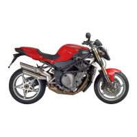
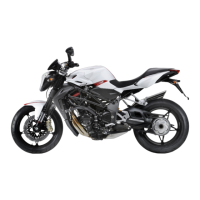
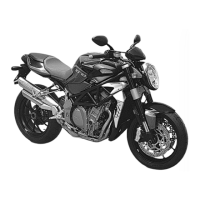
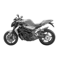
The MV Agusta motorcycle is a high-performance vehicle designed for road use. Its primary function is to provide a thrilling and reliable riding experience, supported by advanced engineering and safety features. The manual details the various components and systems that contribute to this function, including the engine, braking system, electrical system, and user interface.
The motorcycle's controls are intuitively designed for ease of use. The ignition switch (29) is the primary control for powering the vehicle on and off, with positions for "LOCK," "P" (parking), "OFF," and "ON." Once the ignition is on, the starting procedure involves engaging the clutch lever (19) and pressing the START button (24). For cold starts, the CHOKE lever (26) is used to enrich the fuel mixture, aiding in engine ignition in cooler conditions.
The instrument cluster, or dashboard, provides crucial information to the rider. The tachometer (10) displays engine RPM, while the speedometer (15) shows the vehicle's speed. The gear display (11) indicates the currently engaged gear. Various warning lights and indicators are present to alert the rider to potential issues or operational statuses. These include the tyre pressure indicator (1), turn indicator light (2), high beam warning light (3), battery charge indicator (4), engine oil pressure warning light (5), neutral indicator (6), and reserve fuel indicator (7). The coolant thermometer (12) monitors engine temperature, with a blinking segment indicating low temperature and a blinking upper segment indicating high temperature.
User interaction with the dashboard is facilitated by the "SET" button (8) and "OK" button (9), which allow for navigation and selection within the display. The mileage counter (16) tracks total distance covered, while trip counters (17, 18) allow for tracking shorter distances.
Lighting functions are controlled by the low/high beam button (23) and the high beam flasher button (20). Turn indicators are operated via the turn indicator switch (22). The HAZARD button (14) activates all turn indicators simultaneously for emergency situations. Auditory signals are provided by the horn button (21).
The braking system is crucial for safety, with the front brake lever (27) controlling the front brake. The throttle twist grip (28) controls engine speed and power output. The engine stop switch (25) provides an immediate means to shut off the engine in emergencies.
The manual outlines several key usage features to ensure safe and efficient operation of the MV Agusta motorcycle. Before each ride, a "Check list" is provided, covering essential inspections such as tyre pressure and tread depth, engine oil level, brake fluid level, coolant level, functionality of lights and signals, fuel level, and the presence of registration documents. This pre-ride check is critical for preventing potential issues during operation.
The starting procedure is detailed for both cold and hot engine conditions. For cold starts, the CHOKE lever (26) is used in conjunction with the START button (24). Once the engine is warm, the CHOKE lever should be disengaged. The manual explicitly warns against starting the engine indoors due to exhaust fumes.
Troubleshooting flowcharts are a significant usage feature, guiding the rider through common problems such as the engine not starting, the engine shutting off during riding, engine overheating, the alternator not charging the battery, low oil pressure, lights not working, and issues with the horn, speedometer, or dashboard warning lights. These flowcharts provide a systematic approach to diagnosing and resolving issues, often directing the user to check specific components or contact an authorized service center. For example, if the engine does not start, the flowchart prompts the user to check the engine stop switch (25), gear engagement, side stand position, starting procedure, fuel tank level, fuse F1, battery charge, and key code recognition.
The manual also highlights the importance of recognizing warning lights. Specific warnings are given for lights that illuminate or blink in red, indicating a serious issue that requires immediate attention, such as stopping the vehicle and contacting an MV Agusta Service Centre. This proactive warning system is a critical safety feature.
Maintenance is a core aspect of ensuring the longevity and performance of the MV Agusta motorcycle. The manual provides a schedule of maintenance operations based on mileage intervals, ranging from 1,000 km (600 mi) to 36,000 km (22,400 mi), each designated with a service coupon (A through G). It strongly advises that these operations be performed by an authorized MV Agusta Service Centre.
A key maintenance feature is the section on "Replacing the fuses." The manual explains that malfunctions can be caused by non-integrity of fuses and provides instructions on how to check and replace them. It differentiates between the battery recharge fuse and the service fuses. The battery recharge fuse (40 A) is located under the driver's saddle and requires rotating a key and lifting the saddle to access. The service fuses are located under the pillion, and spare fuses are stored in the tool bag within the glove compartment. A detailed list of service fuses (F1 to F7) is provided, specifying their amperage and the components they protect (e.g., fuel pump, injectors, high beam, low beam, starter relay, turn indicators, horn, tail light, lambda sensor, display, speed sensor, solenoid secondary air valve, position lights, power unit, electric fans).
Crucially, the manual includes warnings regarding fuse replacement:
The troubleshooting sections also implicitly guide maintenance by directing users to check fluid levels (engine oil, brake fluid, coolant), battery charge, and the condition of bulbs. While not providing detailed repair instructions for complex components, it empowers the user to perform basic checks and identify when professional intervention is required. The emphasis on contacting an authorized service center for most issues underscores the importance of specialized knowledge and tools for maintaining the motorcycle's advanced systems.
| Displacement | 798 cc |
|---|---|
| Transmission | 6-speed |
| Fuel System | Electronic fuel injection |
| Frame | Tubular steel trellis |
| Rear Brakes | Single disc |
| Fuel Capacity | 16.5 l |
| Front Brake Details | Dual 320mm floating discs, 4-piston calipers |
| Front Brakes | Double disc |