EasyManua.ls Logo

mycom 250SUD

Default Icon
179 pages
To Next Page IconTo Next Page
To Previous Page IconTo Previous Page
Loading...
Chapter 5 Maintenance and Inspection
UD-series Screw Compressor 5.5 Reassembly
5-53
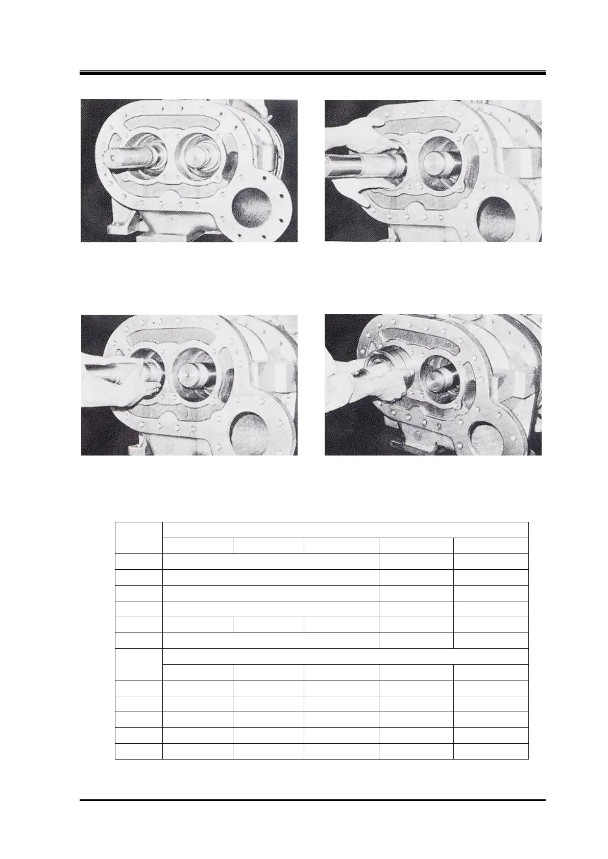
Clearance of thrust bearing Install Thrust Bearing Spacer
e) At this time, measure and confirm the end clearance of the rotor.
The tolerances must fall
within the following ranges:
Use the methods described below to measure the end clearance.
Install the Thrust Bearing Alignment spacer Bearing assembly
Table 7 End clearance
Unit: mm
Model
For single stage (high stage)
S
M
L
LL
XL
125
0.03
0.05
-
-
160
0.04
0.06
-
-
200
0.05
0.07
-
-
250
0.08
0.11
-
-
320
0.17
0.21
0.20
0.24
0.23
0.27
0.26
0.30
-
400
0.24
0.30
-
-
Model
For booster (low stage)
S
M
L
LL
XL
160
0.20
0.22
0.22
0.24
0.24
0.26
-
-
200
0.26
0.30
0.28
0.32
0.31
0.35
-
-
250
0.40
0.44
0.45
0.49
0.50
0.54
0.55
0.59
-
320
0.70
0.76
0.73
0.79
0.77
0.83
0.81
0.87
-
400
0.70
0.80
0.75
0.85
0.80
0.90
0.85
0.95
0.90
1.00

Table of Contents

Related product manuals