5-9
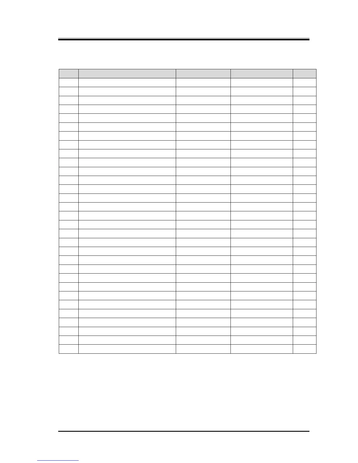
Table 5-8 Replacement parts of i160*
P/N Part name Code No. Remarks Qty
6 Gasket, Strainer Cover CS00900-I160 i160 t=0.5 2
7-1 O-ring see Note 1 PA12-150 JIS B 2401 G150 1
7-2 O-ring see Note 1 PA12-140 JIS B 2401 G140 1
12 Gasket, Bearing Head CS01200-I160 i160 t=0.5 1
17 Gasket, Bearing Cover CS01700-I160 i160 t=0.5 1
23 Gasket, End Cover CS02300-I160N i160 t=1.0 1
27-1 Radial Bearing M CS02800-FM160M NU2311ET7 2
27-2 Radial Bearing F CS02800-FM160FCT NU2312ET7 2
30
Balance Piston see Note 2
CS03000-I160 i160 1
33
Sleeve, Balance Piston see Note 2
CS03300-I160 i160 1
35 O-ring see Note 1 PA11-024 JIS B2401 P24 2
38-1 Thrust Bearing M CS03800-FM160P 7311B Shared with FM160 1
38-2 Thrust Bearing F CS03800-160P 7312B Shared with 160 1
40-1 Lock Washer NG32-011 AW11 1
40-2 Lock Washer NG32-012 AW12 1
49 O-ring see Note 1 PA12-090 JIS B 2401 G90 1
50
Oil Seal see Note 2
CS05000-160VD 160*** (S55×70×9) 1
52 Gasket, Seal Cover CS05200-160N 160*** t=0.5 1
93 Gasket, Suction Flange PL300-125 ANSI 300 # 5" 1
96 Gasket, Discharge Flange PL300-080 ANSI 300 # 3" 1
100
Mechanical Seal Assembly see Note 3
CS10002-160EBS 160V BBSE 1set
150-1 O-ring see Note 1 PA12-110 JIS B 2401 G110 1
150-2 O-ring see Note 1 PA12-115 JIS B 2401 G115 1
216-2 Flange Gasket, Oil Inlet Port CR72000-025N MYCOM 25A (Male) 1
237-1 Torsional Slip Washer M CS23700-FM160M FM160 1
237-2 Torsional Slip Washer F CS23700-160 160*** 1
395 Gasket, Unloader Cover CS39500-I160 i160 t=1.0 2
480 Strainer Element see Note 2 CS48000-I160 i160 #150 Φ160×200 1
489 Valve Seat CS48900-I160 i160 1
491 Check Valve Shaft see Note 2 CS49100-I160 i160 1
495 O-ring see Note 1 PA11-007 JIS B 2401 P7 1
Note 1: The part code of the O-ring is the one assigned to NBR-70-1 which is standard material.
Note 2: When checking each part (No.30, 33, 50, 480, 491) If a special malfunction is not seen, it is
possible to use in the continuation.
Note 3: Mechanical seal assembly (No.100) should be replaced if any defect is found during inspection.
Actually, however, it is sometimes difficult to find out defects on the sliding surface only through visual
inspection. In such circumstances, MAYEKAWA recommends to replace it with a new one.
Also, if it is difficult to stop the compressor operation except for scheduled inspections, MAYEKAWA
recommends replacing No.100 in the same way.
 Loading...

