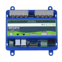
MULTIPOINT CONTROL BOX 8
INSTALLATION MANUAL
3
Multipoint Wall Switches
Multipointwallswitchesareavailablein2,3,4,5,6,7and8zonecongurations,and
connect to the control box module via a synchronous data bus.
Each wall switch has one socket which connects directly to the control box module.
The 2, 3 or 4 button wall switches (MPWS234) are set to the required number of zones
by positioning a jumper on the back of the wall switch during installation.
The 5 and 6 button (MPWS56), and 7 and 8 button (MPWS78) wall switches are also
set to the required number of zones using a jumper during installation.
The top button (determined by the overlay used - not the switches on the hardware)
corresponds to the motor output 1 on the control box module.
A 2 button wall switch will control motor outputs 1 and 2 only. A 5 button wall switch will
control motor outputs 1, 2, 3 4 and 5 only. The 8 button wall switch controls all 8 zones.
Motorised Dampers
Motorised dampers connect directly to the control box module via the motor output
sockets.
Component Positioning
The control box module and wall switch expansion modules can be positioned on or
near the systems air handling unit, or in the mechanical services switchboard.
The wall switch should be mounted in a central location within the air conditioned space.
Theyaredesignedtobeushmountedtoacavitywall,butmaybesurfacemounted
through the use of a mounting block not less than 15mm deep.
The motorised dampers can be mounted at the takeoff point of the rigid duct or mounted
in-lineintheexibleduct.
Commissioning
Prior to applying power to the system, double check all wiring connections. Ensure
motors are connected to motor outputs and touchpads to touchpad outputs.
Set the spill zone(s) if required. To set the spill zone(s), move the respective switch in
the spill zone DIP switch block on the control box to the ‘on’ position. Any number or
combination of zones may be set as spill zones to suit the installation. Refer to the A/C
unitspecicationstodeterminetheminimumairowthatisrequired.
Thespillzone,whenset,ensuresairowacrossthecoilismaintainedatacceptable
levels. If the user turns all zones off, the designated spill zones are forced to open.
Turnallzoneson,thenturnontheindoorfantoensureairisowingtoeachzone.
Turn each zone off in turn to ensure the zone dampers are functioning correctly and the
zones match the names on the wall switch. Turn all zones off to ensure the spill zone is
functioning (if set).

 Loading...