Do you have a question about the Myzone Multipoint Control Box 8 and is the answer not in the manual?
Details the components of the Multipoint Control Box 8 zone system, including the control box module and transformer.
Specifies the power input and line frequency requirements for the controller.
Outlines the operating temperature, altitude, and humidity limits for the system.
Defines the specifications for data and motor cables used with the control box.
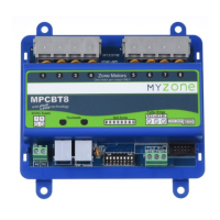
Describes the MPCBT8 module as the core component, detailing its connections and mounting options.
Details the available Multipoint wall switches and their zone configuration options.
Explains how motorised dampers connect directly to the control box module.
Provides guidance on where to position the control box module, expansion modules, and wall switches.
Outlines the essential steps for testing and setting up the system after installation.
Explains how to set the number of zones controlled by wall switches using jumper blocks.
Details how to operate individual zones using the wall switch buttons and their LED indicators.
Illustrates the physical wiring connections between the control box, motors, transformer, and wall switches.
Provides step-by-step guidance on how to properly crimp cables and insert plugs into sockets.
| Brand | Myzone |
|---|---|
| Model | Multipoint Control Box 8 |
| Category | Control Unit |
| Language | English |