MULTIPOINT CONTROL BOX 8
INSTALLATION MANUAL
4
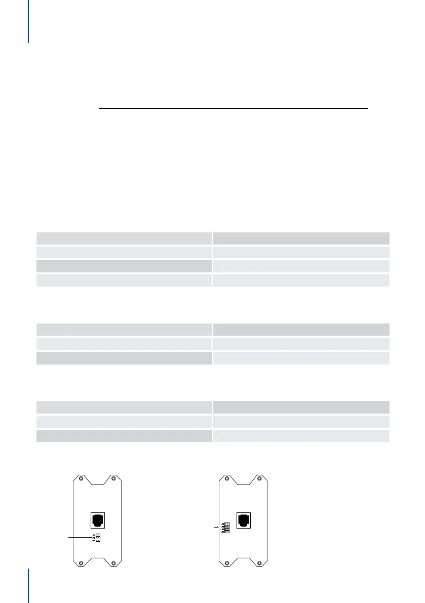
Wall Switch Zone Number Selection:
The jumper blocks on the back of the wall switches are used to set the number of zones
controlled by the switch.
The top button (determined by the overlay used - not the switches on the hardware) on
each wall switch corresponds to zone 1 output on the control box module.
Example
For a 5 button wall switch the top 2 buttons and the bottom button of the wall switch
hardware are disabled by placing the jumper across the pins at JP4 on the back of the
wall switch. See image next page.
Once the number of zones for the wall switch has been selected place the zone labels
in the appropriate position on the front of the switch prior to sticking the overlay in place.
Wall Switch Zone Number Assignment - MPWS234:
MPWS234 Jumper Position Zones Controlled
JP1 (Top) 1, 2, 3 and 4
JP2 (Middle) 1, 2 and 3
JP3 (Bottom) 1 and 2
Wall Switch Zone Number Assignment - MPWS56:
MPWS56 Jumper position Zones Controlled
JP3 (2nd from Bottom) 1, 2, 3, 4, 5 and 6
JP4 (Bottom) 1, 2, 3, 4, and 5
Wall Switch Zone Number Assignment - MPWS78:
MPWS78 Jumper position Zones Controlled
JP1 (Top) 1, 2, 3, 4, 5, 6, 7 and 8
JP2 (2nd from Top) 1, 2, 3, 4, 5, 6 and 7
MPWS234 MPWS56 & MPWS78
Zone Number
Selection Jumpers
Zone Number
Selection Jumpers
 Loading...