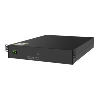
ID Switch
ID Switch indicates the unique ID code for each battery module.
It's required to assign a unique ID to each battery module for
normal operation.
We can set up the ID code for each battery module by rotating
the PIN number on the ID switch. From number 0 to 9, the
number can be random; no particular order.
If more than one battery module in the parallel system, the
battery pack connected to the power module is the Master battery
and the ID code should be set as 0. The ID code of the remaining
battery module MUST be unique. Not the same number for 2
battery modules in parallel system.
Maximum 10 battery modules can be operated in parallel.
 Loading...