Chapter 6 Filling the Lubricant
58
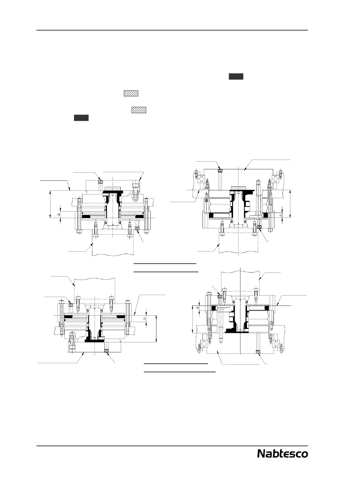
6.2.2. Vertical shaft installation
For the E series and original series
The amount of lubricant the reduction gear requires and the target range (the areas in the
diagram) when the reduction gear is installed in the vertical shaft are indicated in Fig. 6-3. Each amount
does not include the space (the areas in the diagram) on the motor mounting side. Therefore, if
there is a blank space, also fill the space. Leave a space about 10% of the total volume of the internal
capacity of the reduction gear (the areas in the diagram) and the space on the motor mounting
side (the areas in the diagram). For the amount of lubricant for the products not included in the
catalog, contact our service representative individually.
Vertical shaft installation
(with shaft facing downward)
Vertical shaft installation
(with shaft facing upward)
Shaft installation
component
Shaft installation
component
Tapped hole for
injecting/draining
grease
Tapped hole for
injecting/draining
grease
Tapped hole for
injecting/draining
grease
Tapped hole for
injecting/draining
grease
Tapped hole for
injecting/draining
grease
Tapped hole for
injecting/draining
grease
Tapped hole for
injecting/draining
grease
Tapped hole for
injecting/draining
grease
Lubricant
surface
Target range
Target range
Target range
Target range
 Loading...