Appendix: Design Scheme of Input Gear
70
Design Scheme of Input Gear
For models RV-□E and RV-□, we have a variety of standard input gears for each speed ratio that can be additionally
machined by the customers. Please machine and install the standard input gear based on the customer’s intended use, by
referring to the following examples. Note: For the model and reduction speed ratio provided with the standard input gears,
refer to “Dimensions of standard input gear” on page 75.
Standard input gear specifications
Material
Heat treatment Carburizing, quenching and tempering
Surface hardness HRC58 to 62 (excluding the carburizing prevention range)
Material SCM415 Normalizing or equivalent material
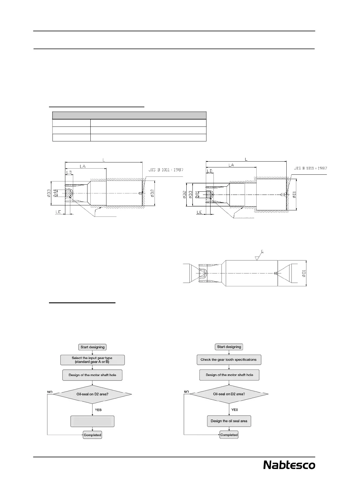
<Standard input gear A: For small motors> <Standard input gear B: For large motors>
Note: The above drawing shows the shape before the additional machining is performed. Check the dimensions of each
section in the “Dimensions” table on pages 69 and 70.
• Reference for additional machining
Standard input gears come equipped with center holes and
ground boss outer diameter (D1).
When modifying them, use the center hole or boss outer
diameter (D1) as the reference surface.
Design of the input gear
Please refer to the chart below. Use it as a reference when the customer designs an input gear on their own.
Design flow
When modifying the standard input gear When manufacturing a special input gear
Appendix
Manufacture a special
60°C center hole, type A
Carburizing prevention range
60°C center hole, type A
Carburizing prevention range
Refer to page 69
Refer to pages 69 to 71
Refer to pages 77
and 78
Refer to pages 69 to 71
Refer to page 71