Appendix: Design Scheme of Input Gear
71
Selection of the input gear type
There are the following two types of standard input gear:
Standard input gear A: For small motors
Standard input gear B: For large motors
Select the type of input gear to be used by referring to the tables below.
Applicable motor shaft diameters for standard input gear
(Unit: mm) (Unit: mm)
Model
Standard input
gear A
Standard input
gear B
Model
Standard input
gear A
Standard input
gear B
RV-6E ø16 or less
RV-160E,
RV-160
Less than ø28 ø28 or more
RV-20E,
RV-15
Less than ø14 ø14 or more
RV-320E,
RV-320
Less than ø32 ø32 or more
RV-40E,
RV-30
Less than ø19 ø19 or more
RV-450E,
RV-450
Less than ø42 ø42 or more
RV-80E,
RV-60
Less than ø24 ø24 or more RV-550 ø40 or less
RV-110E ø24 or less
Note: Some models have only standard input gear A.
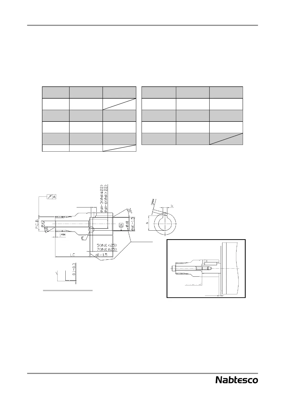
Design of the motor shaft hole
<(Design example 1: For straight shafts (attached to motor shaft tip)>
Note 1. When a tapped hole is used for the motor shaft, fix the input gear to the motor shaft with a bolt.
2. For the bolt through hole diameter (d3), radial runout, and the shaft hole position (LC), refer to “Dimensions after
modification” in the “Dimensions” table on pages 69 and 70.
3. If the bolt through hole diameter (d3) is larger than the center hole diameter on the tooth surface side (d4), it is
necessary to process the carburized surface. In such a case, confirm the applicable tools and processing conditions,
etc.
4. The clearance hole diameter for the keyway (d5) is “keyway width (k) + 2 mm”, approximately. [The clearance hole
diameter must be larger than the keyway width (k).]
5. Design the motor shaft hole diameter (d1) according to the motor shaft diameter to be used.
6. For the keyway width (k) and keyway height (a), refer to the specifications of the key to be used.
d5 drill
Drill both at
the same time
Detailed drawing of section E
Installation
reference surface