Chapter 8 Maintenance and inspection
68
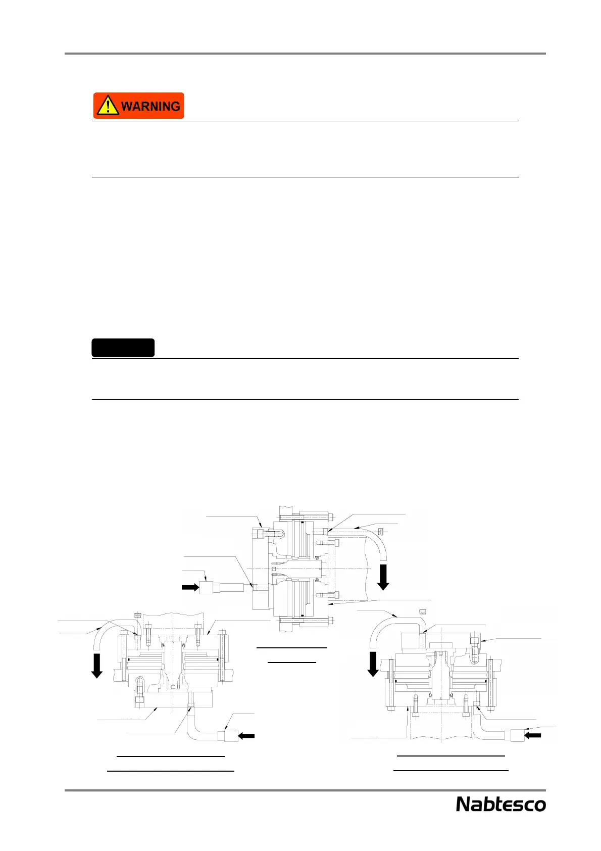
Fig. 8-2
Vertical shaft installation
(with shaft facing downward)
Vertical shaft installation
(with shaft facing upward)
Horizontal shaft
installation
component
injecting/draining
injecting/draining
injecting/draining
grease (drain
lubricant)
injecting/draining
grease (supply side)
Tapped hole for injecting/
injecting/
draining grease
mounting flange
mounting flange
Do not use the motor to rotate the output shaft of the reduction gear for safety, if possible. If the motor
is used by necessity, run the motor at a low speed and never touch the rotation section. Otherwise,
you could be caught by the rotation section, which will result in serious injury.
• Repeat steps 3 to 8 until the reduction gear is filled with the same amount of lubricant as that was
Step 9
drained.
• It is recommended that the inside of the reduction gear is flushed so that the lubricant can be
Step 10
replaced more efficiently.
• Remove the injector from the tapped hole on the supply side, and attach a hexagon socket head cap
plug to the tapped hole on the drain side. Calculate output shaft conversion and set the motor
rotation speed so that the output shaft rotation speed is 5 to 10 rpm. Then, rotate the motor for
about one minute.
Set the rotation speed based on the output shaft conversion by taking the customer’s operation
conditions into account.
• Perform steps 1 and 9 again.
Step 11
• Attach the hexagon socket head cap plugs to the tapped holes for injecting/draining grease.
Step 12
Replace the seal tape with a new one.
• Wipe off the lubricant adhering to the surrounding completely.
Step 13
Important