Inputs can be driven from either 3.3-V or 5-V devices. This feature allows the use of these devices as translators
in a mixed 3.3-V/5-V system environment.
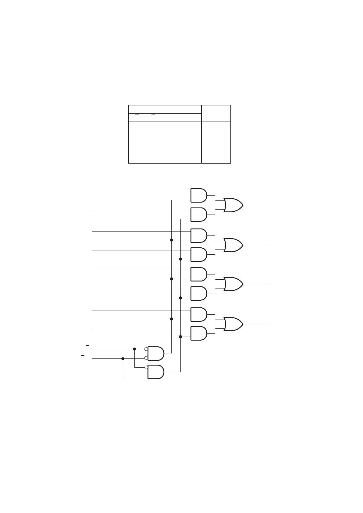
FUNCTION TABLE
INPUTS
OUTPUT
G A/B A B
Y
H X X X L
L LLX L
L LHX H
L HXL L
L H X H H
logic diagram (positive logic)
2
3
5
6
11
10
14
13
15
1
G
A/B
4B
4A
3B
3A
2B
2A
1B
1A
4
7
9
12
1Y
2Y
3Y
4Y
Pin numbers shown are for the D, DB, J, NS, PW, RGY, and W packages.
MULTIPLEXERS : IC49(74VHC157FT)
2-33