Do you have a question about the Nakamichi OMS-7 and is the answer not in the manual?
Configures voltage input for the device.
Lists included packing items and available owner's manuals.
Safety precautions for handling the laser pickup to prevent static damage.
Step-by-step guide for physically replacing the laser pickup assembly.
Outlines initial rough adjustments after pickup replacement.
Shows locations of adjustment potentiometers and test points on PCBs.
Illustrates adjustment screws and lock screws on the pickup assembly.
Important notes and precautions before performing adjustments.
Step-by-step technical procedures for various calibration points.
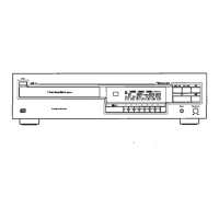
Overview of the disc mechanism assembly and its main components.
Exploded view and parts list for the front panel assembly.
Exploded view and parts list for the chassis assembly.
Exploded view and parts list for the main disc mechanism assembly.
Exploded view and parts list for a sub-assembly of the disc mechanism.
Exploded view and parts list for the analog processor unit.
Mounting diagram and component list for the photo transistor circuit board.
Mounting diagram and component list for the photo diode circuit board.
Mounting diagram and component list for the open end switch circuit board.
Mounting diagram and component list for the FL indicator circuit board.
Mounting diagram and component list for the auto power control circuit board.
Mounting diagram and component list for the analog processor circuit board.
Visual representations and functional descriptions of key integrated circuits.
Visualizations of signal patterns at critical test points for diagnostics.
Exploded view and parts list for the remote control transmitter's mechanism.
PCB layout and component list for the remote control's circuit board.
Electrical schematic for the remote control transmitter circuit.