Do you have a question about the Nakamichi MB-4s and is the answer not in the manual?
Specifies the product code assigned to the unit.
Lists the regions or countries for which the product is intended.
Safety notices regarding product operation, leakage current, and laser beam exposure.
Instructions for grounding human body and equipment during laser pickup servicing.
Guidelines for discharging static electricity before handling sensitive components.
Specifications for soldering irons suitable for laser pickup repair.
Procedures for aligning and positioning gears within the side chassis R section.
Steps for correctly positioning the tray assembly on the mechanism unit.
Instructions for connecting the test unit to the Main P.C.B. for adjustments.
Procedure to check and adjust laser current, measuring current flow into R101.
Steps to adjust the VCO frequency using VR105 and a frequency counter.
Procedure to adjust VR101 for optimal waveform amplitude and clarity.
Steps to adjust VR102 for proper E-F balance waveform center level.
Procedure to adjust VR104 to equalize waveform amplitudes for tracking gain.
Steps to adjust VR103 to equalize waveform amplitudes for focus gain.
Performing functional tests using specific test disc programs to ensure proper operation.
Overall schematic and parts list for the mechanism assembly.
Exploded view and parts list for the front panel assembly.
Exploded view and parts list for the main mechanism assembly.
Exploded view and parts list for the right side chassis section.
Exploded view and parts list for the main chassis section.
Exploded view and parts list for the drive unit section.
Mounting diagram and detailed parts list for the main printed circuit board assembly.
Diagram and parts list for the transformer printed circuit board assembly.
Diagram and parts list for the power switch printed circuit board assembly.
Diagram and parts list for the key input printed circuit board assembly.
Diagram and parts list for the display printed circuit board assembly.
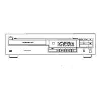
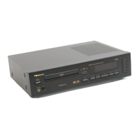
Technical specifications for the main CD player unit.
Technical specifications for the infrared remote control unit.
List of accessories included with the CD player unit.