2. Splicing Design
3. Functional Specifications
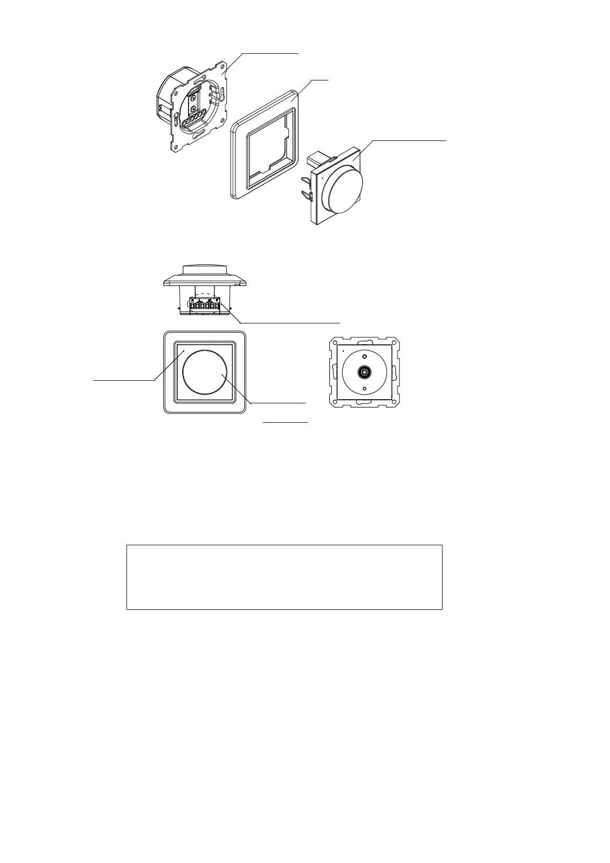
3.1 Status Indicator
3.1.1 Indicator lights blue and flash: Enter to Zigbee mode connection.
3.2 Input and Output Terminals
3.2.1 N: Input terminal (Connect the neutral and live wire “N”)
3.2.2 L: Input terminal (Connect the live wire “L”)
3.2.3: Output terminal (Connect the bulbs)
3.2.4 P: Signal input terminal (Connect the self-reset switch-output terminal)
3.3 Push-button Rotary Switch
3.3.1 Turn on: Short press one time when in OFF.
3.3.2 Turn off: Short press one time when in ON.
3.3.3 Dimming:
a. Turn clockwise to increase the brightness.
b. Turn counterclockwise to decrease the brightness.
c. Long press to adjust the brightness when in ON status.
Release and long press again to change the direction of the dimming brightness.
3.3.4 Continuous short press two times when in ON/OFF can quickly turn to the full brightest.
3.3.5 Setting the ideal min brightness when in on status,continuous short press six times and the
lamp flash three times.
3.3.6 Setting the ideal max brightness when in on status,continuous short press eight times and the
lamp flash three times.
3.3.7 Network mode: Continuous short press seven times when in ON status.
Operation Component
Drive Component
Panel
②
Input and Output Terminals
③Push-button
Rotary Switch
①Status Indicator
Short press: Within 0.5s
Long press: Over 0.5s
Continuous short press: Each interval of short press should
within 1s