Do you have a question about the Nastec Vasco V209 and is the answer not in the manual?
Critical warnings regarding electrical hazards, disconnection, grounding, and proper disposal procedures.
Table listing different models with voltage, current, and power ratings for selection.
Details on operating frequency, ambient temperature, altitude, and current handling capacity.
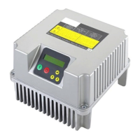
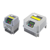
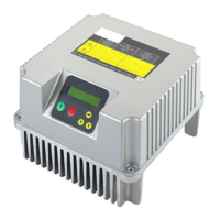
Visual representations and weight information for different product sizes (Size 1, 2, 3).
Wiring diagram and cable stripping recommendations for the V209,214 power board.
Wiring diagram and cable stripping recommendations for the V218,225 power board.
Wiring diagram and cable stripping recommendations for the V230,238 power board.
Wiring diagram and cable stripping recommendations for the V306,309,406,409 power board.
Wiring diagram and cable stripping recommendations for the V314-430 power board series.
Wiring diagram and cable stripping recommendations for the V338-485 power board series.
Description of analog inputs, digital inputs/outputs, and RS485 communication ports.
Required upstream protections and measures for electromagnetic compatibility.
Guidance on using filters and adjusting frequency for long motor cables.
Components and procedures for mounting the controller onto motors for sizes 1 and 2.
Components and procedures for mounting the controller onto the motor for size 3.
Components for wall mounting and important installation warnings.
Basic diagram of the system and recommendations for pressure tank selection.
Requirements for pressure sensors and connection to analog inputs.
Connecting sensors and setting logic for differential pressure measurement.
Setting control parameters for maintaining differential pressure.
Explanation of parameter levels, passwords, and the LCD display.
Step-by-step guide for setting up the controller for the first time.
Details on setting language, units, motor type, and control modes.
Features, calibration, and adjustment of FOC motor control.
Display messages, status indicators, and how to access controller menus.
Settings for control modes, alarm limits, set values, and compensation.
Settings for motor voltage, current, frequency, protection, and COMBO operation.
Configuration of analog/digital inputs, outputs, and sensor scaling.
Configuration of MODBUS address, baudrate, and data format.
Descriptions and solutions for common alarm types and protection events.
Explanations for specific alarms like sensor faults, value limits, communication, and keyboard errors.
Methods for controlling DOL pumps and operational scenarios.
Enabling COMBO mode, RS485 connection, and master/slave setup.
Procedures for handling master failure and ensuring slave replacements.
Solutions for LCD, power, sensor, oscillation, and pump control problems.
Details needed to provide to technical assistance for problem resolution.
List of directives and regulations the product conforms to.
| Supply Voltage | 24 VDC |
|---|---|
| Digital Inputs | 8 |
| Analog Inputs | 4 |
| Analog Outputs | 2 |
| Protection Class | IP20 |
| Controller Type | PLC |
| Communication | RS485 |
| Operating Temperature | -10°C to 50°C |