Do you have a question about the Nat AA34-200 and is the answer not in the manual?
Overview of the manual's content for product description, design features, and specifications.
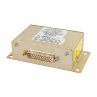
Details the AA34 Universal Radio Interface's function in aircraft audio systems.
Highlights key features like microphone excitation, relay keying, and sidetone generation.
Covers electrical, physical, and environmental details of the AA34 Universal Radio Interface.
Details input power, input/output signals, frequency response, and distortion.
Provides dimensions, weight, mounting, material, and connector types for the unit.
Lists operating and survival temperature, altitude, humidity, shock, and vibration ratings.
States FAA TSO authorization and applicable standards for product approval.
Defines the different AA34 models and their specific functionalities.
Overview of unpacking, inspection, installation, and post-installation procedures.
Instructions for unpacking, inspecting the unit for shipping damage, and checking contents.
Details the product warranty terms, conditions, and voidance clauses.
States that maintenance is 'on condition' only, with no periodic maintenance required.
Guides on the correct methods and precautions for installing the AA34 Universal Radio Interface.
Crucial safety warnings to prevent damage or improper operation during installation.
Important advisories on wiring, shielding, and component placement for optimal performance.
Specifies wire selection, routing, segregation, and connection requirements.
Procedures for verifying correct installation and operation before service release.
Tests for correct power input and ground continuity before connecting the unit.
Steps to confirm proper function of the AA34 and connected radios after power-up.
Details how to configure and connect the AA34 for optimal performance.
Describes access and function of external potentiometers for level adjustments.
Explains the RX LEVEL, MIC LEVEL, and S/T LEVEL potentiometers on the rear.
Details switches S1, S2 for mic bias/blocking and C1/C2 for mic path selection.
Configuration options for the AA34-200 model, including jumpers and switches.
How to set the mic output level using a jumper for 30mV or 200mV.
Setting the receiver gain to high or low using a jumper.
Configuring the RX output impedance to 600Ω or 150Ω via a jumper.
Configuration options for AA34-300/301 models, focusing on audio output impedance.
Setting audio output impedance for 8Ω or 600Ω loads using jumper JP2.
Setting mic output impedance for 8Ω or 150Ω loads using jumper JP1.
Lists the installation kit (AA34-IKC) and its components needed for installation.
References documents containing interconnect and mechanical installation drawings.
Overview of functional and operational procedures for the AA34 Universal Radio Interface.
Explains the interface capabilities and notes that internal adjustments are for qualified personnel.
| Brand | Nat |
|---|---|
| Model | AA34-200 |
| Category | Recording Equipment |
| Language | English |