AA34 Series Universal Radio Interface
SM36 Installation and Operation Manual
Section 2 Rev: 1.01 Issue 4 Page 2-5
ENG-FORM: 805-0121.DOT
CONFIDENTIAL AND PROPRIETARY TO NORTHERN AIRBORNE TECHNOLOGY LTD.
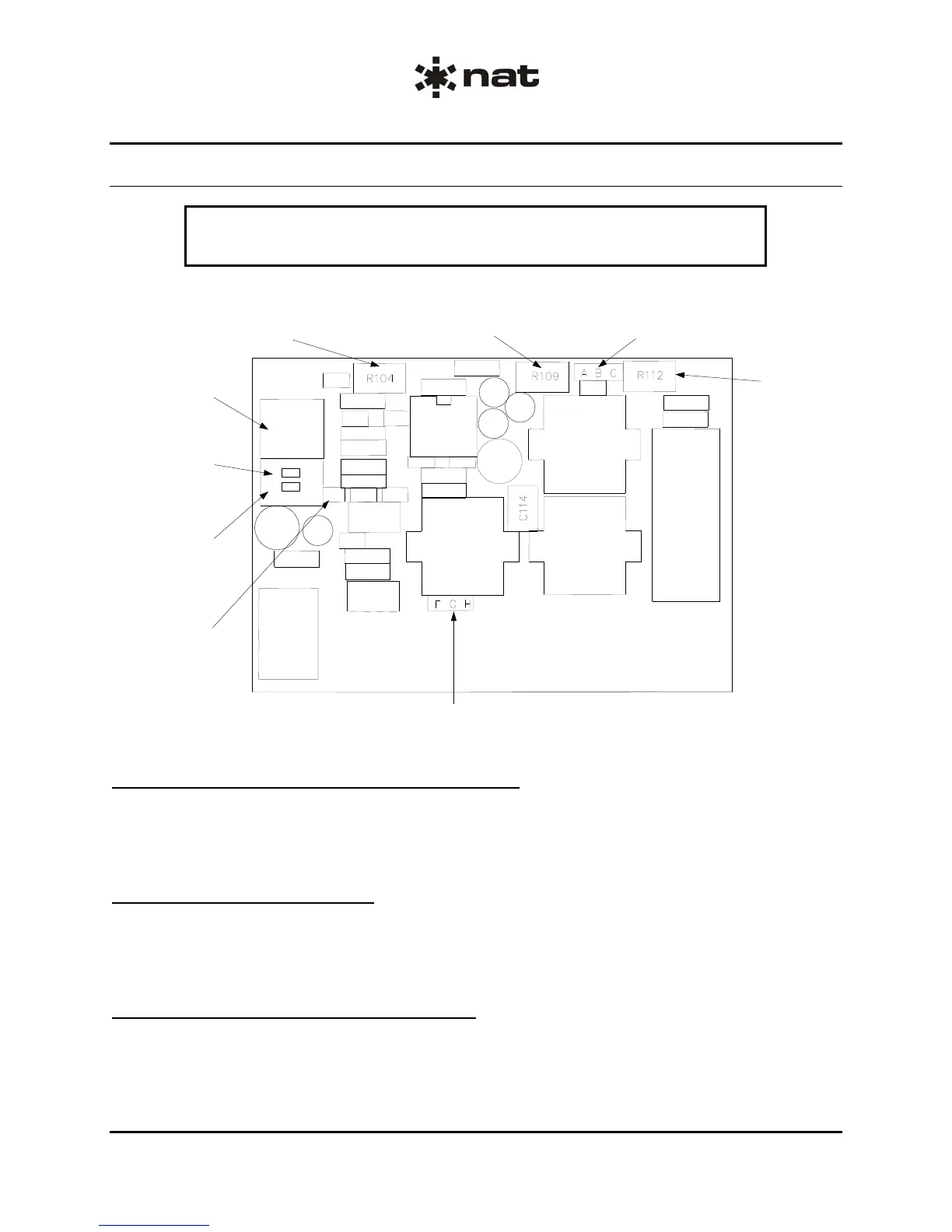
2.5.2 Internal Adjustments (AA34-200 only)
CAUTION:
The AA34 Series Universal Radio Interface contains static sensitive devices.
Proper ESD handling procedures must be followed to prevent damage to the unit.
D E
C1/C2: Mi
Isolation/ Direc
Switch
S1: Mi
DC Bias
S2: Mic Outpu
Blocking
Capacito
RX High Gain
Jumpe
RX Output Impedance Jumper
(normally soldered F-G)
etone
eve
Adjustment
Mic Output Level
Adjustment
-B-C Mic
Output Jumper
RX Level
djustment
OPEN
S1 S2
C1
2.5.2.1 30/200 mV Mic Output Level Adjustment
Remove the cover from the AA34-200 and locate the Mic Output jumper. When the jumper is connected
across pins A and B, the unit level is set at 200 mV. When connected across B and C, the unit level is set
to 30 mV. (The default setting is A – B).
2.5.2.2 RX Gain Adjustment
Remove the cover from the AA34-200 and locate the RX Gain jumper. When the jumper is connected
across pins D and E, the unit is set to operate at high gain. When not connected, the unit is set to
operate at low gain (default setting).
2.5.2.3 RX Output Impedance Adjustment
Remove the cover from the AA34-200 and locate the RX Output Impedance jumper. The factory default
is 600 Ω (jumper soldered across F and G). If connected across G and H, the unit is set to 150 Ω.