5. Pump Sizing: A suitable pump must be field-
provided for circulation of water between Model
VW heaters and the storage tank. This pump
must be sized to avoid excessive temperature
rise and to provide correct flow for water
hardness conditions. Specifications in Table IV
include allowance for 30 feet of piping and normal
fittings between heater and tank.
6. Install pump in a cool location. When pump is
installed where it is subjected to excessive heat,
the life of the pump will be shortened. Heat will
embrittle motor insulation and dry out bearing
lubricants. If the pump motor is equipped with
thermal protection, excessive heat may trip the
thermal switch and shut down the pump 2J.
intermittently. This could result in rapid scaling of
the heater.
IMPORTANT: Check oil level in pump before starting.
Oil pump every three (3) months. Fill bearing
assembly to lower level of overflow vent. Add five (5)
or six (6) drops of oil to front and rear of motor. Use
20W non-detergent oil. Pumps located in excessively
hot or dusty locations should be oiled once a month.
Self lubricating pumps do not require oiling.
7. The pump should be accessible for lubrication,
inspection and service.
8. If pump is designed for floor mounting, install
securely on concrete block or pad at least six (6)
inches above floor level. This will prevent
flooding of motor when floor is washed. Be sure
that floor mounted pumps are not suspended
from piping and that piping is plumbed to avoid
strain on the pump casing.
2I. Water Pressure
It is very important that water pressure in the
system be maintained above 30 psi. If the
system pressure should drop below this, the
vapor pressure of water in the suction side of the
pump can cause hammer and cavitation in the
pump and damage the heater through lack of
water circulation. If for any reason the water
supply is turned off temporarily to service a
piece of equipment, the manual gas valve on
the Model IW should be closed until the water
pressure has been restored and the lines bled of
accumulated air. If the heater fails to fire when it
is turned back on, it may be airlocked. To
eliminate the airlock, open the pressure relief
valve and allow air to bleed out until water flows.
As soon as full circulation is resumed, the
entrained air will be carried out through the hot
water faucets.
2J. Tank Installation
1. Be sure the floor is waterproof and structurally
capable of supporting the tank when it is filled
with water.
2. The tank should be placed so that manholes,
inspection covers, nameplates and drain valves
are accessible.
3. Be sure the tank is suitable for the water in the
system. Some water is corrosive and requires a
protected tank with a special lining.
14
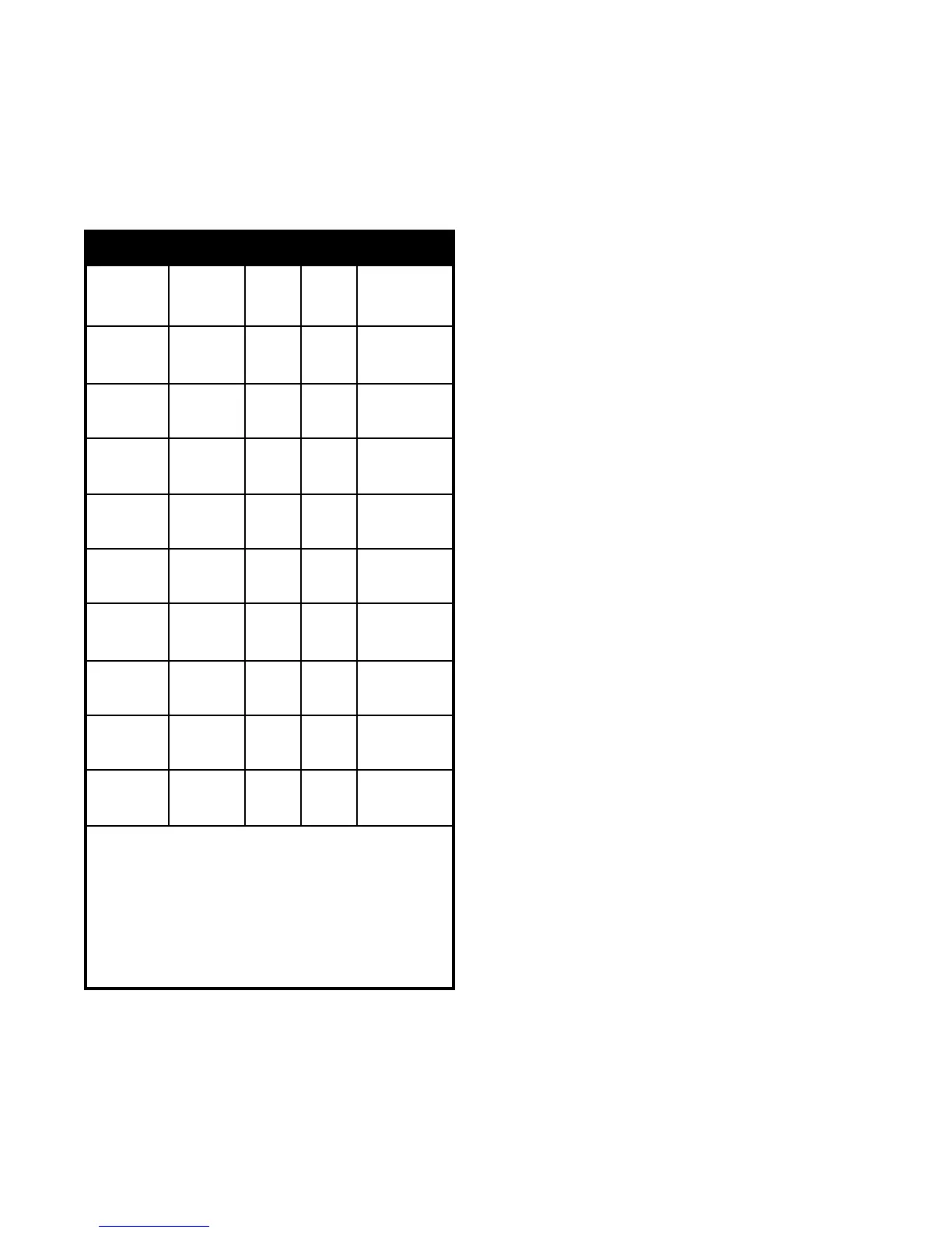
Table IV. Pump Performance Requirements
Flow Head* Temp. Rise
Water Rate Loss Across
Model Category (GPM) (ft.) Heater, (F)
Soft 45 5.0 17
500 Normal 68 9.9 11
Hard 90 15.7 8
Soft 45 5.1 20
600 Normal 68 10.0 14
Hard 90 15.9 10
Soft 45 5.3 24
715 Normal 68 11.0 16
Hard 90 17.8 12
Soft 45 5.4 30
850 Normal 68 11.1 20
Hard 90 18.1 15
Soft 45 3.9 35
1010 Normal 68 7.5 23
Hard 90 11.7 18
Soft** 68 7.8 27
1200 Normal 68 7.8 27
Hard 90 12.2 21
Soft** 68 8.1 32
1430 Normal 68 8.1 32
Hard 90 12.6 24
Soft** 68 8.3 37
1670 Normal 68 8.3 37
Hard 90 13.0 28
Soft** 90 13.5 30
1825 Normal** 90 13.5 30
Hard 90 13.5 30
Water Category Grain Hardness per Gal.
Soft 1 through 7.5
Normal 7.6 through 17
Hard Over 17
* Pressure drop includes loss through 30 feet of pipe and normal fittings
when heater is installed with storage tank. Pipe and fittings are assumed to
be 2" on Models (500-850) and 2 1/2" on Models (1010-1825)
** To prevent erosion, these models must be ordered with cupro-nickel heat
exchanger tubes.