C
D
B
K
J
C
H
C
H
J
180°F
Water
To
Bldg.
Conventional
Tank
140°F Water
To Bldg.
To
Drain
To Drain
Cold
Water
To
Drain
Pump
PW Series
VW Series
140°F Water
Return From
Bldg.
180°F Water
Return From
Bldg.
Cold Water
Pump
PW Series
VW Series
16
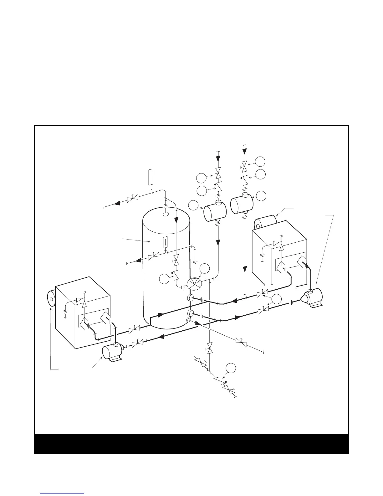
Figure 17 – Two-Temperature Hot Water Supply System with Vertical Tank for Models VW and PW Water Heaters
recommended pipe size, a larger pump may be
required. Consult the factory if in doubt.
6. Install a pipe in the tank drain fitting that goes to a
floor sink, and install a drain valve. If a floor sink
is not available, install a hose bib.
7. Hot water tanks in an existing installation are
likely to have a deposit of silt on the bottom.
Therefore, it is important to extend the pump
suction pipe in the tank to a position near the top.
Pipe the return from the heater to the bottom of
the tank.
4. If the tank is glass-lined, it should be equipped
with a suitable magnesium anode. It is good
practice to replace the anode when it is
approximately 50% used. The factory warranty
on a glass-lined tank will be void if a satisfactory
anode is not in place at the time of a failure or if it
is consumed by cathodic action.
5. Make sure the tank connections in the heater-
tank circulating loop are the proper size as listed
in Section 2H. If tappings are smaller than the
LEGEND
B – Check Valve
C – Check Valve
D – Tempering Valve
H – Throttling Valves in Building Loop Returns
J – Circulating Pump for Return Loop
K –Service Valves to Isolate Heater and Pump for Service