15
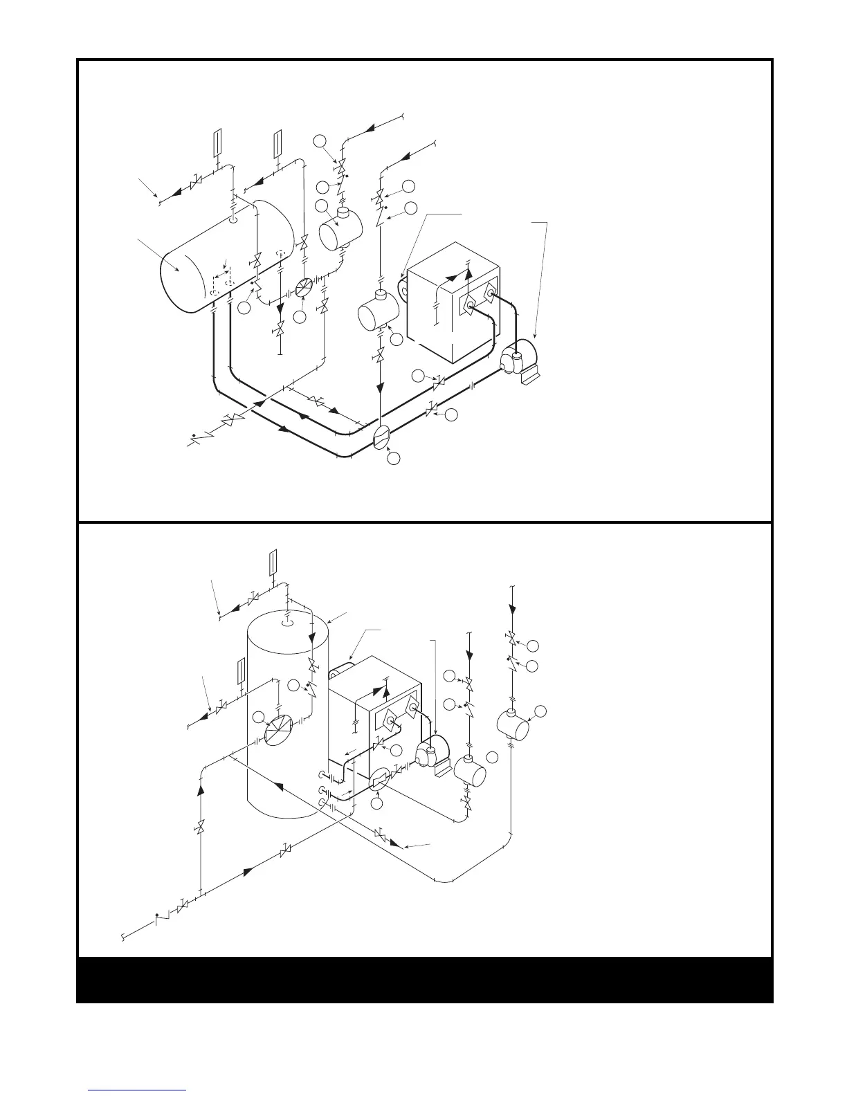
Figure 16 – Two-Temperature Hot Water Supply System (Model VW or PW)
Legend
B – Check Valve in Hot Water Supply to
Tempering Valve
C – Check Valve in Return Line from Building Loop
D – Tempering Valve
E – Venturi (Suction) Tee
H – Throttling Valves in Building Loop Returns
I – Circulating Pump for 180° Building Loop
J – Circulating Pump for 140° Building Loop
K – Service Valves to isolate Heater and Pump for
Service
With
Horizontal
Tank
With
Vertical
Tank
Cold
Water
180°
Water
To Bldg.
Conventional
Tank
To
Drain
24" Min.
To Drain
Pump
PPW Series
PVW Series
H
140°
Water
To Bldg.
140° Water
Return
From Bldg.
180° Water
Return
From Bldg.
H
C
C
B
D
I
K
K
E
J
Cold
Water
180°
Water
To Bldg.
Conventional
Tank
To Drain
140°
Water
To Bldg.
To
Drain
Pump
PW Series
VW Series
180°Water
Return
From Bldg.
140°Water
Return
From Bldg.
B
D
E
K
C
H
C
H
I