Do you have a question about the National Comfort Products Comfort Pack CPE U Series and is the answer not in the manual?
| Brand | National Comfort Products |
|---|---|
| Model | Comfort Pack CPE U Series |
| Category | Air Conditioner |
| Language | English |
Installation and repair must be performed by qualified individuals meeting National Codes.
Covers high voltage, grounding, and copper wire usage to prevent shock and damage.
Advises caution for scroll compressors and warns against improper evacuation procedures.
Prohibits flammable materials near the unit and restricts mobile home applications due to safety.
Stresses following instructions, prohibits oxygen use, and covers general installation.
Explains the coding system used for model numbers, detailing cooling capacity and heating options.
Details various options like grille types, filter doors, and chassis designations within model numbers.
Describes heating sequences, contactor operation for U11 and U12 models, and fan sequencing.
Explains unit fault conditions and cooling blower operation delays.
Instructions on removing shipping bolts and installing plugs to prevent air leakage.
Specifies through-the-wall installation, floor height, garage placement, and grille clearance.
Details connecting primary and secondary drain lines and traps for proper drainage.
Mandates adherence to all electrical codes and consulting local authorities.
Provides step-by-step guidance for safely removing and installing the unit's chassis.
Ensures installation meets codes and electrical data matches the unit's rating plate.
Emphasizes through-the-wall installation only and warns against improper unit orientation.
Stresses sealing the air divider to prevent leakage and maintain unit performance.
Details providing support and caulking around the unit and wall sleeve for proper installation.
Instructions for installing the unit into an optional wall sleeve with sealant.
Details connecting the primary drain line, trap, and ensuring proper pitch for drainage.
Provides instructions for installing and priming the secondary drain trap for overflow protection.
Specifies minimum vertical and horizontal clearances between units for optimal airflow.
Details minimum height above floor and garage installation requirements for safety.
Discusses lintel support for masonry walls and flashing the wall opening.
Advises maintaining clear air inlets/outlets and addresses decorative grilles affecting performance.
Warns against placement near fumes, in dead-end hallways, and notes service access requirements.
Recommends locating units away from bedrooms to avoid operational noise disturbances.
Mandates wiring compliance with codes and specifies operating voltage limits for warranty.
Guides thermostat placement for accurate sensing and mentions low voltage wiring.
Outlines line voltage, grounding, and low voltage connections for system hookup.
Provides a table specifying maximum wire lengths for low voltage wiring based on wire size.
Illustrates low voltage wiring connections between the unit and thermostat for U-12 models.
Details voltage requirements, nameplate correspondence, and code compliance for power supply.
Presents the high voltage schematic and the requirement for a separate disconnect switch.
Illustrates fuse box layout and fuse sizes for 5, 7, and 10KW models.
Shows the fuse box layout and fuse sizes for the 15KW model.
Stresses regular filter maintenance for optimal performance and energy efficiency.
Discusses removing the cooling chassis for servicing and the benefits of spare chassis.
Notes permanently lubricated motors and the sealed refrigeration system.
Recommends annual cleaning of components and notes electrical controls need no routine service.
Outlines steps for filling out forms and calling for verification before removing a warranty compressor.
Provides detailed electrical data including voltage, amps, and motor ratings for different models.
Lists cooling and heating capacities, EER ratings, and heating KW for various models.
Lists parts for the unit's cabinet with corresponding part numbers and applicable models.
Lists parts for the unit's chassis with part numbers and applicable models.
Details replacement parts for CP41.0, CP41.5, CP42.0, and CP42.5 chassis models.
Outlines warranty periods for parts and heat exchangers and customer registration requirements.
Lists conditions voiding warranty and limits liability for damages.
Defines exclusive warranty terms and limits remedies to repair, replacement, credit, or refund.
Details customer obligations for registering, reporting, and authorizing warranty claims.
Outlines requirements for warranty claims on heat exchangers, compressors, and other parts.
Provides guidelines for securely packaging and marking returned compressors and parts for warranty.
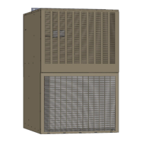
Introduces the Comfort Pack, its design, and installation benefits.
Lists model types, heating capacities, cabinet materials, color, and voltage.
Covers airflow, filter access, slide-out chassis, and secondary drain.
Discusses building heat loss considerations, controls, sales, and technical support.