Appendix A Device-Specific Information
M Series User Manual A-78 ni.com
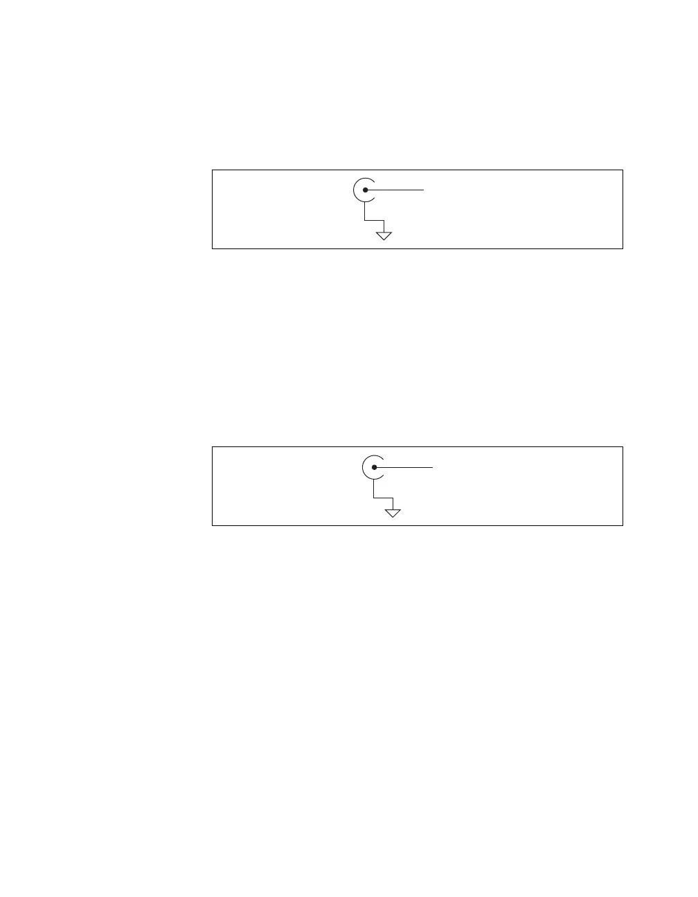
Digital I/O and Timing I/O
You can access digital I/O and timing I/O signals on the BNC connectors
labeled PFI <0..7>/P1.<0..7>. Figure A-35 shows the DIO/TIO circuitry on
the USB-6251 BNC.
Figure A-35. Digital I/O and Timing I/O Circuitry
Refer to the Connecting Digital I/O Signals section of Chapter 6, Digital
I/O, and the Connecting PFI Input Signals section of Chapter 8, PFI, for
more information.
APFI
You can access the analog programmable function interface signal on the
BNC connector labeled APFI 0. Figure A-36 shows the APFI circuitry on
the USB-6251 BNC.
Figure A-36. Analog Programmable Function Interface Circuitry
Refer to the Triggering with an Analog Source section of Chapter 11,
Triggering, for more information.
PFI
x
/P1.
D GND
APFI
AI GND
 Loading...