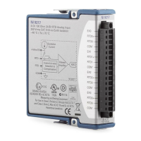
The NI 9401 is an 8-channel, TTL digital input/output module designed for use in various industrial and commercial applications. It serves as a versatile interface for connecting digital devices to a system, offering configurable input/output channels and robust protection features.
Function Description:
The NI 9401 provides eight digital input/output (DIO) channels, each referenced to a common (COM) line. These channels are grouped into two ports: one containing channels 0, 1, 2, and 3, and the other containing channels 4, 5, 6, and 7. Each digital port can be independently configured in software for either input or output operation. It's important to note that all four channels within a port must share the same line direction. The module is designed to connect to a 25-pin DSUB connector for these digital input/output channels.
The module supports various digital devices, including SPI devices, and can be configured for different input and output scenarios. For instance, an SPI device can be connected with output signals assigned to one port (e.g., DIO3:0 configured for output) and input signals assigned to the other port (e.g., DIO7:4 configured for input). Similarly, it can interface with multiple digital devices like a TTL signal source (DIO0 as input), a switch (DIO1 as input), and an LED (DIO7 as output).
Important Technical Specifications:
- Input/Output Characteristics:
- Number of channels: 8 DIO channels
- Default power-on line direction: Input
- Input/output type: TTL, single-ended
- Digital Logic Levels:
- Input:
- Voltage: 5.25 V max
- High (VIH): 2 V min
- Low (VIL): 0.8 V max
- Output:
- Sourcing 100 µA: 4.7 V min
- Sourcing 2 mA: 4.3 V min
- Sinking 100 µA: 0.1 V max
- Sinking 2 mA: 0.4 V max
- Maximum Input Signal Switching Frequency (per channel):
- 8 input channels: 9 MHz
- 4 input channels: 16 MHz
- 2 input channels: 30 MHz
- Maximum Output Signal Switching Frequency (per channel with 1 mA, 50 pF load):
- 8 output channels: 5 MHz
- 4 output channels: 10 MHz
- 2 output channels: 20 MHz
- I/O Propagation Delay: 100 ns max
- I/O Pulse Width Distortion: 10 ns typ
- Input Current (0 V ≤ Vin ≤ 4.5 V): ±250 µA typ
- Input Capacitance: 30 pF typ
- Input Rise/Fall Time: 500 ns max
- Overvoltage Protection (channel-to-COM): ±30 V max on one channel at a time; however, continued use at this level will degrade the life of the module.
- MTBF (Mean Time Between Failures): 1,244,763 hours at 25 °C; Bellcore Issue 2, Method 1, Case 3, Limited Part Stress Method. Contact NI for MTBF specifications at other temperatures or for MIL-HDBK-217F specifications.
- Power Requirements (from chassis):
- Active mode: 580 mW max
- Sleep mode: 1 mW max
- Thermal Dissipation (at 70 °C):
- Active mode: 580 mW max
- Sleep mode: 1 mW max
- Physical Characteristics:
- Safety:
- Maximum Voltage (Channel-to-COM): ±30 V max on one channel at a time, Measurement Category I. This is the maximum voltage that can be applied or output between any channel and COM without damaging the module or other devices.
- Isolation Voltages:
- Channel-to-channel: None
- Channel-to-earth ground (Continuous): 60 VDC, Measurement Category I
- Channel-to-earth ground (Withstand): 1,000 Vrms, verified by a 5 s dielectric withstand test
- Hazardous Locations:
- U.S. (UL): Class I, Division 2, Groups A, B, C, D, T4; Class I, Zone 2, AEx nC IIC T4
- Canada (C-UL): Class I, Division 2, Groups A, B, C, D, T4; Class I, Zone 2, Ex nC IIC T4
- Europe (DEMKO): EEx nC IIC T4. Evaluated as EEx nC IIC T4 equipment under DEMKO Certificate No. 03 ATEX 0324020X. Marked Ex II 3G, suitable for Zone 2 hazardous locations. For Gas Group IIC hazardous locations or ambient temperatures of -40 °C ≤ Ta ≤ 70 °C, must be used in an NI chassis evaluated as EEx nC IIC T4, Ex nA IIC T4, or Ex nL IIC T4 equipment.
- Environmental:
- Operating temperature (IEC 60068-2-1, IEC 60068-2-2): -40 °C to 70 °C
- Storage temperature (IEC 60068-2-1, IEC 60068-2-2): -40 °C to 85 °C
- Ingress protection: IP 40
- Operating humidity (IEC 60068-2-56): 10% to 90% RH, noncondensing
- Storage humidity (IEC 60068-2-56): 5% to 95% RH, noncondensing
- Pollution Degree: 2
- Maximum altitude: 2,000 m
- Indoor use only.
- Shock and Vibration (requires panel mounting):
- Operating vibration (Random, IEC 60068-2-64): 5 grms, 10 to 500 Hz
- Operating vibration (Sinusoidal, IEC 60068-2-6): 5 g, 10 to 500 Hz
- Operating shock (IEC 60068-2-27): 30 g, 11 ms half sine; 50 g, 3 ms half sine; 18 shocks at 6 orientations
Usage Features:
- Configurable Ports: The NI 9401 allows independent software configuration of its two digital ports for either input or output, providing flexibility for various applications.
- Protection Features: Each channel includes a pull-down resistor and incorporates overvoltage, overcurrent, and short-circuit protection. Overcurrent protection limits the current for switching DIO channels or sourcing the output load. If an overcurrent condition occurs, the module's power supply voltage drops until the condition is resolved or the module turns off. In this state, it can accept new line direction configurations and output state data but cannot pass valid input data to the software.
- Sleep Mode: The module supports a low-power sleep mode, which helps conserve energy and reduce heat dissipation. The availability and implementation of sleep mode depend on the chassis the module is plugged into. Users should refer to the chassis manual and software help for details on enabling sleep mode.
- EMC Compliance: To ensure specified electromagnetic compatibility (EMC) performance, the module must be operated with shielded cables and accessories. A clamp-on ferrite bead (National Instruments part number 711627-01) must be installed on the cable as close to the module as possible.
- Marine Applications: Some modules are Lloyd's Register (LR) Type Approved. For marine applications, shielded cables and a metal enclosure are required to meet radio frequency emission requirements. Suppression ferrites must be installed on power supply inputs near power entries to modules and controllers, and power supply and module cables must be separated on opposite sides of the enclosure.
Maintenance Features:
- Cleaning: The module can be cleaned by wiping it with a dry towel.
- Repair: In case of product damage, the NI 9401 should be returned to National Instruments for repair to ensure the safety protection built into the product is not compromised.
- Documentation: Comprehensive operating instructions and specifications are provided, along with information on installing, configuring, and programming the system. Additional resources, including software help and online product certification, are available on the ni.com website.
- Support: National Instruments offers extensive technical support through its website (ni.com/support), including troubleshooting guides, application development resources, and email/phone assistance from NI Application Engineers. Corporate headquarters and worldwide offices provide further support.