16 | ni.com | NI PXIe-5653 Calibration Procedure
6. Use the signal source analyzer to measure the peak power and frequency at the peak with
the following parameter settings:
• Set frequency reference level: Spectrum Analyzer Ref Level value returned by
NI-RFSG
• Set center frequency: Spectrum Analyzer Center Frequency value returned by
NI-RFSG
• Frequency counter mode: 0.1 Hz resolution
• Measure power level: maximum peak power as measured
7. Adjust the NI 5653 Reference Clock using the measurements taken in step 6 for the
Measured Ref Out Frequency Peak and Measured Ref Out Power parameters.
8. Repeat steps 6 and 7 until the Reference Clock Calibration Complete parameter returns
a value of TRUE.
9. Close the external calibration session. Store the results to the EEPROM on the device.
Adjusting YIG Frequency
Complete the following procedure to adjust the NI 5653 YIG coarse frequency performance
using a signal source analyzer.
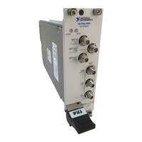
1. Connect the NI 5653 LO1 front panel connector to the signal source analyzer RF IN front
panel connector.
2. Connect the signal source analyzer REF IN rear panel connector to the rubidium frequency
reference output connector.
3. Configure the signal source analyzer as follows:
• Center frequency: 3 GHz
• Reference level: 20 dBm
• Frequency span: 1 GHz
• Resolution bandwidth: 50 kHz
• Reference clock source: External
4. Create a new external calibration session using the appropriate password.
5. Create a new YIG frequency calibration session.
6. Use the signal source analyzer to measure the peak power and frequency at the peak with
the following parameter settings:
• Set frequency span: Spectrum Analyzer Frequency Span value returned by
NI-RFSG
• Set center frequency: Spectrum Analyzer Center Frequency value returned by
NI-RFSG
• Measure frequency: Frequency at peak power as measured
• Measure power level: Maximum peak power as measured
7. Adjust the YIG frequency using the measurements taken in step 6 for the Measured LO1
Frequency and Measured LO1 Power parameters.

 Loading...