© National Instruments | 1-5
RMC-8356 User Manual
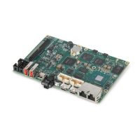
Figure 1-2. Rear View of the RMC-8356
The rear of the chassis includes the following features:
• Power Supply—350 W Platinum Level Power Supply.
• I/O Back Panel—Rear I/O ports.
• Expansion Card Slot—Slot for one expansion card (requires pre-installed riser card).
• Rack Ear Brackets—Attaches server chassis to the rack.
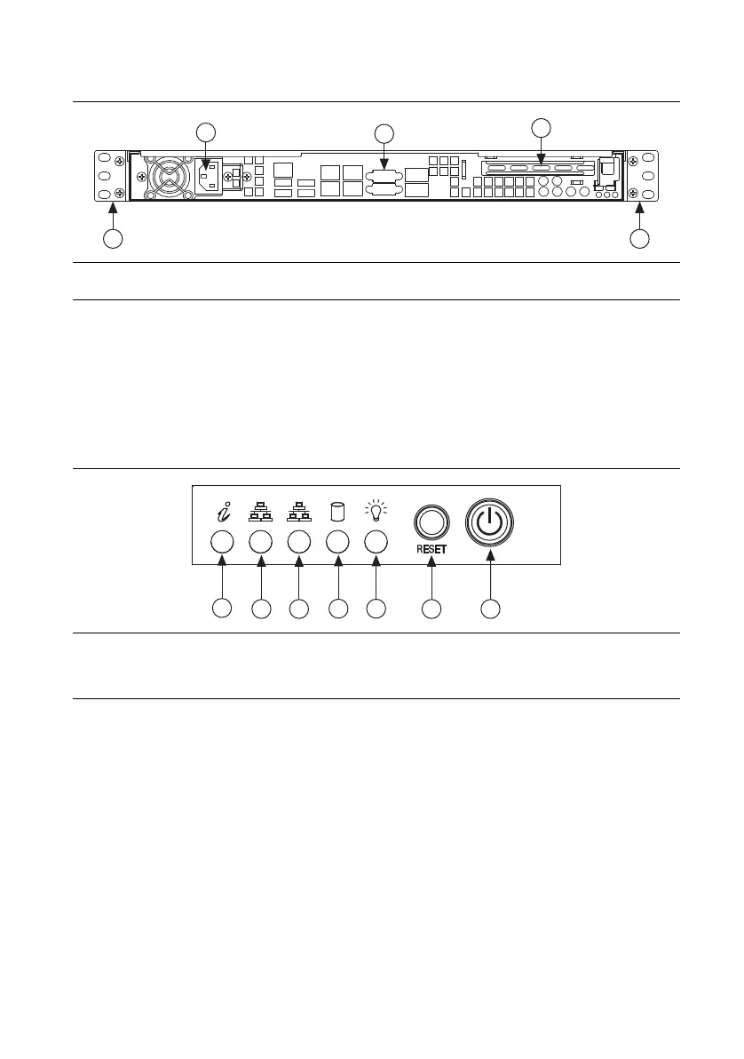
Figure 1-3. Control Panel Features
The control panel includes the following LEDs:
• Overheat/Fan Fail LED—Flash indicates a fan failure. Solid indicates overheat condition.
• NIC2 LED—Flash when there is activity on LAN port 2.
• NIC1 LED—Flash when there is activity on LAN port 1.
• HDD LED—Flash when there is hard drive activity.
• Power LED—Solid when system is operating.
• Reset Button—Reboots the system.
• Power Button—Removes the main power but maintains standby power. To perform many
maintenance tasks, you must also unplug system before servicing.
1 Power Supply
2 I/O Back Panel
3 Expansion Card Slot
4 Rack Ear Brackets
1 Overheat/Fan Fail LED
2 NIC2 LED
3 NIC1 LED
4 HDD LED
5 Power LED
6 Reset Button
7 Power Button
1
2
3
4
4
1
2 3
4 5
6 7

 Loading...