© National Instruments | B-9
RMC-8356 User Manual
Speaker/Buzzer
On the JD1 header, pins 1-4 are for the speaker and pins 3-4 are for the buzzer. If you wish to
use an external speaker, connect its cable to pins 1-4.
SGPIO Headers
The I-SGPIO1 (Serial General Purpose Input/Output) header is used to communicate with the
enclosure management chip on the backplane.
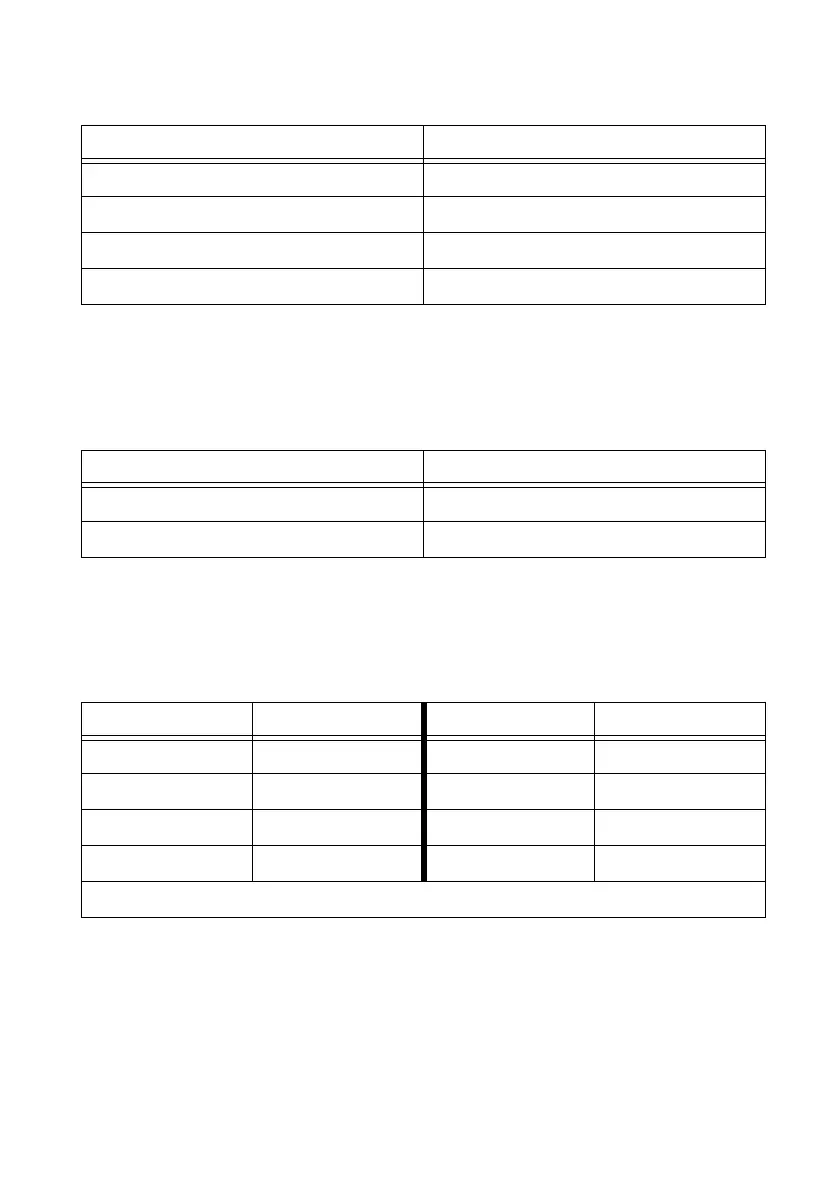
Table B-9. Fan Header Pin Definitions
Pin Definition
1 Ground (Black)
2 2.5 A/+12 V (Red)
3 Tachometer
4 PWM_Control
Table B-10. Speaker Connection Pin Definitions
Pin Setting Definition
Pins 1-4 Speaker
Pins 3-4 Buzzer
Table B-11. SGPIO Header Pin Definitions
Pin Definition Pin Definition
1 NC 2 NC
3 GND 4 Data
5 Load 6 GND
7 Clock 8 NC
NC = No Connection

 Loading...