The
HRO
Amateur Communications Receiver
T
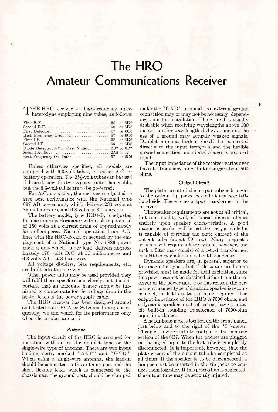
HE HRO receiver is a high-frequency super-
heterodyne employing nine tubes,
as
fallows:
6eeondR.F
..............................
5s
or6D6
First
Deteotor.
...........................
.57
or
6C6
High
Frequency
OsciUator
.................
.57
or
6C6
First1.F
..................................
58
or6D6
Seoond1.F
................................
58
oieD6
Diode Detector,
AYC,
First Audio.
.........
.2B7
or
6B7
SeoondAudio
............................. 2A5or42
Beat
Frequency
Osoilistor.
................
.57
or
6C6
Unless otherwise specified, all models are
equipped with 6.3-volt tubes, for either A.C. or
battery operation. The 2%-volt tubes
ean be used
if
desired, since the two typesareinterchangeable,
but the 6.3-volt tubes
are
to
be preferred.
For A.C. operation, the receiver
is
adjusted to
give best performance with
the
National type
697 AB power unit, which delivers 230 volts at
75
milliamperas, ~nd 6.3 volts at 3.1 amperes.
The battery model, type HRO-B, is djusted
for maximum performance with a plate potential
of 180 volts at a current drain of approximately
55 milliamperes. Normal operation from A.C.
lines with the
HRO-B
can be secured by the em-
ployment of a
National type No. 5886 power
pack, a unit which, under load, delivers approx-
imately 170 volts D.C. at 50 milliamperes and
.
6.3 volts A.C. at 3.1 amperes.
All
voltage dividers, bias requirements, etc.
are built into the receiver.
Other power units may be used provided they
will fulfil these specifications closely, but it is im-
portant that an adequate heater supply be fur-
nished to
compensate for the voltage drop in the
heater leads
of
the power supply crthle.
The HRO receiver
has
been designed around
and tested
with
RCA or Sylvania tubes; conse-
quently, we can vouch for its performance only
when these tubes are used.
Antenna
The input circuit of the HRO is arranged for
operation with either the doublet type or the
single-wire type of antenna. There are two input
binding posts, marked "ANT"
and "GND."
When using a single-wire sntenna, the lead-in
should be connected
to
the antenna post and the
short flexible lead, which is connected
to
the
chassis near the ground post, should be clamped
under the "GND" terminal. An external ground
connection
mav
or
mav not be neoessarv. deoend-
,.
.
Lng
iupcm
rht ~r~if~ll~rt~~:~.
TL
ground
id
uiuaUy
rlcsi~.able svilett receiviug \r.avcle:.grlu ab~vz
100
n,cte<>, hut ior
STAY
,iragtl.r bcl>.v
80
lueter~, rhv
use of a ground may actually weaken signals.
Doublet antenna feeders should be connected
directly
to
the input terminals and the flexible
ground connection, mentioned above,
is
not used
at all.
The
Input impedance of the receiver varies over
the total frequency range but averages about 500
ohms.
Output
Circuit
T1.e plarc circuit
oi
the cutl,ut rubc is broughr
ro the cutl~ut
t~p
jack I>mted
~t
the
rehr
left-
I.:xl.rl -iJc. 'l'hcre is no
<,UlDUr
rr3nzformer
m
rhe
receiver.
The speaker requirements are not at all
critical,
5
but tone quality will, of course, depend almost
'
entirely upon speaker characteristics.
A
good
*
'-
magnetic speaker will be satisfactory, provided it
is capable of carrying the plate current of the
output tube (about 30 ma.). Many magnetic
speakers will require a filter system, however, and
such a
filter
may consist of a l-to-1 transformer,
or a 30-henry choke and a l-mfd. condenser.
Dynamic speakers are, in general, superior to
the magnetic types, but if these are used some
DravisiOn must be made for field excitation. since
this
power
ramor be oornincd eitller ilo~u the re-
ccivcr or t1.c pon.sr unir.
K,r
rhi. reat"", rLe per-
manent rnsgner r).p20i
dyunmi;
apesker
i>
rerorn-
mended, no field excitation being requ~red. The
output impedance of the HRO is 7000 ohms, and
a dynamic speaker must, of course, have a snita-
ble built-in coupling transformer of 7000-ohm
input impedance.
A headphone
jack is located on the front panel,
just below and to the right of the "S"-meter.
This jack
is
wired into the output of the pentode
section of the 6B7. When the phones are plugged
in,
the signal input to the la$t tube is completely
disconnected. It is important, however, that the
plate circuit of the output tube be completed at
all times.
If
the speaker is to be disconnected,
a
jumper must be inserted in the tip jacks to con-
nect them together.
If
this precaution isneglected,
the output tube may be seriously injured.


 To Next Page
 Loading...
