Do you have a question about the Nautilus Hyosung MONiMAX5600 and is the answer not in the manual?
| Model | MONiMAX 5600 |
|---|---|
| Category | Cash Counter |
| Hopper Capacity | 500 notes |
| Connectivity | USB |
| Power Supply | 100~240V, 50/60Hz |
| Noise Level | Less than 60 dB |
Provides the MX5600 maintenance guide for field technicians.
For personnel maintaining MX5600 in bank branches, including field and repair engineers.
Defines terminology, abbreviations, and symbols used throughout the manual.
Lists and defines abbreviations used for ATM components and functions.
Essential safety information for handling the product to prevent injury or damage.
Lists supplementary documents like Operator Manual and Installation Manual.
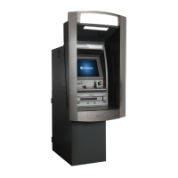
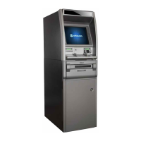
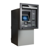
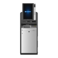
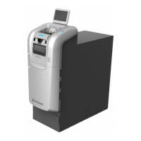
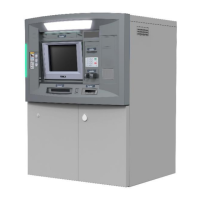
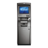
Describes the MX5600 ATM as a lobby type solution, easy to use and service.
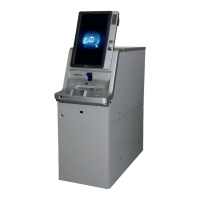
Highlights important specifications of the MX5600T ATM, including hardware and functions.
Introduces the MX5600 as a lobby type ATM and outlines its benefits.
Illustrates the front of the MX5600, identifying key units and fascia components.
Details the hardware configuration and presents a system block diagram.
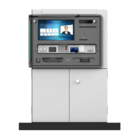
Describes the components of the user handling unit, including card reader and PIN pad.
Details the OPL, including its LCD, privacy pad, and touch screen components.
Provides general specifications for the TFT-LCD display module.
Safety precautions for handling and maintaining the LCD module.
Step-by-step guide for troubleshooting common LCD display issues.
Details general specifications for associated electronic boards and interfaces.
Information on the inverter board's interface and appearance.
Mechanical specs and handling remarks for the touch screen component.
Describes the EPP's function, parts, and troubleshooting common issues.
Explains the functions and operations of the panel control board.
Details the barcode scanner as a CMOS imager for barcode decoding.
Describes the location and function of the motor-driven ATM card reader.
Details procedures for handling card reader problems and verification steps.
Recommends specific items for field repair of the card reader.
Step-by-step guide for diagnosing and resolving card reader faults.
Provides instructions on how to safely clear card jams in the reader.
Details cleaning cycles and methods to prevent card reader problems.
Explains the power supply unit's role in converting AC to DC power for system modules.
Describes LED functions, switch operations, and switch status of the power supply.
Guides on handling problems related to the power supply unit and battery.
Recommends specific items for field repair of the power supply unit.
Explains the battery's function during power failures and system protection.
Describes control electronics components like motherboard, HDD, and ODD.
Labels and describes various components and connectors on the motherboard.
Details specifications for CPU, Chipset, Memory, Storage, LAN, and Audio.
Explains how to set jumpers for correct motherboard configuration options.
Guides on connecting case components like fans, switches, and LEDs to the motherboard.
Step-by-step illustrated guide for safely installing the CPU onto the motherboard.
Step-by-step illustrated guide for installing DDR3 SDRAM modules.
Explains expansion slots and provides instructions for installing add-on cards.
Guides on accessing and configuring the system's BIOS settings.
Describes the HDD and its role as a storage device for OS and program installation.
Describes the ODD and its function for reading installation CDs.
Illustrates the PCI USB cable and its slot connection.
Shows the system fan, its location, and cable connection.
Illustrates the CPU cooler and its cable connection.
Introduces the CDU and its five major modules: Body, Presenter, Feed, Cassettes, and Reject Box.
Shows sectional diagrams illustrating the appearance and dimensions of the cash dispenser.
Lists the fundamental specifications of the cash dispenser.
Describes different types of cash dispensers, such as front and rear access models.
Explains the functions of electromagnetic components like motors, clutches, and solenoids.
Details the various types of sensors embedded in the cash dispenser and their roles.
Presents a block diagram illustrating the controller board's architecture.
Details the main board's cable connections and labeling for assembly.
Lists components for replacement and outlines repair availability.
Provides instructions for replacing various sensors within the CDU.
Guides on replacing major sub-assemblies like the controller board and motors.
Details procedures for replacing cassette latches and push plates.
Highlights the importance of proper adjustment for component lifespan and performance.
Provides instructions for adjusting drive belt tensions to remove slack.
Details the procedure for adjusting the gate shutter solenoid position.
Outlines cleaning cycles and methods for sensors and rollers.
Provides guidelines on lubrication, including oil amount symbols and lubricant types.
Explains dip switch settings for transaction modes and sensor adjustments.
Introduces the receipt printer and provides general precautions for maintenance.
Essential precautions for expert maintenance, disassembly, and lubrication.
Defines regular inspection cycles (M6, Y1) and maintenance intervals.
Lists replacement parts and outlines procedures for disassembling the printer.
Provides a table detailing the available replacement parts for the receipt printer.
Guides on disassembling the receipt printer into sections and major components.
Step-by-step instructions for disassembling the Thermal Print Head (TPH).
Details disassembly for sensors, motor, springs, guide, and PCBA.