89Appendixes
17. Turn on the gas and water supply to the boiler.
18. Measure and adjust the gas/air ratio.
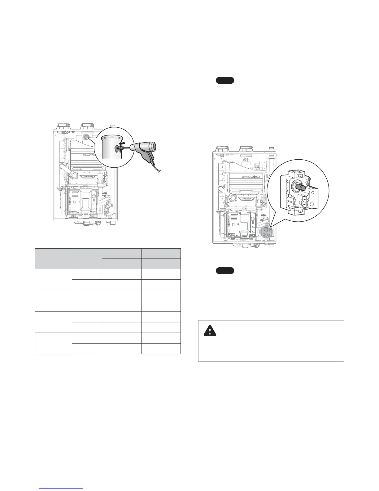
Option 1. Using Combustion Analyzer (recommended)
a. Loosen the screw, rotate the plate and remove the gasket
to access the emissions monitoring port as shown in
Figure 7.
b. Insert the analyzer into the port (Figure 7).
Figure 7. Insert the Analyzer
Model Fuel
High fire Low fire
%CO
2
%CO
2
NHB-055
NG 8.9 9.5
LP 10.2 10.8
NHB-080
NG 8.9 9.5
LP 10.2 10.8
NHB-110
NG 8.9 9.5
LP 10.2 10.8
NHB-150
NG 8.9 9.5
LP 10.2 10.8
Table 2. CO
2
value
(CO
2
values must be within 0.5% of the values listed.)
c. Activate multiple zones and set the boiler to operate at
1-stage MIN mode.
Note
For operation mode selection, refer to “11.5
Setting the Operation Mode” on page 77.
Measure the CO
2
value at low fire.
If the CO
2
value is not within 0.5% of the value listed in
Table 2, the gas valve set screw will need to be adjusted.
If adjustment is necessary, locate the set screw as shown
in Figure 8. Using a
5
/
32
in or 4 mm Allen wrench, turn
the set screw no more than
1
/
4
turn clockwise to raise or
counterclockwise to lower the CO
2
value.
Figure 8. Set Screw Location
Note
The set screw is located behind the screw-on
cover. This must be removed first.
d. Activate multiple zones and set the boiler to operate at
2-stage D. MAX mode (refer to “11.5 Setting the Operation
Mode” on page 77). Measure the CO
2
value at high fire.
If the CO
2
values do not match Table 2 at high fire, do not
adjust the gas valve. Check for the proper Gas Orifice.
DANGER
Improper gas valve settings can cause severe personal injury,
death or substantial property damage.
 Loading...