3
Venting
>
Electrical Connections
>
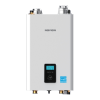
Vent Termination Options
Horizontal vent termination
Interior view
Intake Air
Exhaust Gas
12" (300 mm) min.
Exterior view
Vertical vent termination Sidewall vent termination
12" min. from any
obstruction above,
below, left, or right
12" (300 mm) min.
12" (300 mm) min.
Concentric Vent Termination
Sidewall installation
Combustion Air
Combustion Air
1" (25mm) min
Maintain 12" min.
clearance above
highest anticipated
snow level or grade.
Vent
Roof installation
Vent
Vent
Combustion Air
Maintain 12" min.
(18" min. for Canada)
clearance above
highest anticipated
snow level maximum
of 24" above roof.
Combustion
Air
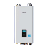
Venting Length
4” pipe venting 3” pipe venting
8
1
3
7
2
Maximum Length 150'
Maximum number
of elbows: 8
3-to-4 inch
6
1
3
4
5
2
Maximum number
of elbows: 6
Maximum Length 60'
· 90˚ elbow = 5 linear feet of venting
· 45˚ elbow = 3 linear feet of venting
· 90˚ elbow = 5 linear feet of venting
· 45˚ elbow = 3 linear feet of venting
Exhaust Vent Piping Materials
· All Navien boilers are Category IV appliances.
· The venting system should be approved for use with Category IV appliances (typically Type BH
Special Gas Vent approved by UL 1738-S636).
· Venting requirements in the USA and Canada are dierent (see below).
Navien recommended venting materials
Locale Recommended Vent Materials
USA
· PVC/CPVC Schedule 40 or 80 (Solid Core)
· Approved Polypropylene (PP)**
· Approved Stainless Steel (SS)***
Canada*
· Type BH Special Gas Vent Class IIA (PVC)
· Type BH Special Gas Vent Class IIB (CPVC)
· Type BH Special Gas Vent Class IIC (Polypropylene/Stainless Steel)
* For installation in Canada, eld-supplied plastic vent piping must comply with CAN/CGA B149.1 (latest
edition) and be certied to the Standard. For Type BH Gas Venting Systems, ULC-S636. Components of this
listed system must not be interchanged with other vent systems or unlisted pipes or ttings. All plastic
components and specied primers and glues of the certied vent system must be from a single system
manufacturer and must not be intermixed with another system manufacturer’s parts.
The supplied vent connector and vent termination are certied as part of the boiler.
** Approved Polypropylene Systems include:
Duravent PolyPro® SW (Rigid): 3PPS-xxx (3”) or 4PPS-xxx(4”)
Duravent PolyPro® (Flexible): 3PPS-FLEXxx (3”), 3PPS-FAM (3” Rigid-to-Flex Male Adapter)
Centrotherm Innoue® SW (Rigid): ISxx03xx (3”) or ISxx04xx (4”)
Hart & Cooley Polyue™ SW (Rigid): 3PF-xx (3”) or 4PF-xx (4”)
Z-Flex Z-DENS SW (Rigid): 2ZDP_(3” or 4")
*** Approved Stainless Steel Systems include:
Duravent FasNSeal® (Rigid): FSA-PVC3 or FSA-PVC4 (3” or 4” PVC to FasN Seal Appliance Adapter),
FSxxxxx03 or FSxxxxx04 (3” or 4”)
Heat Fab Saf-T Vent® EZ Seal: 9301PVC or 9401PVC (3” or 4” PVC/CPVC Outlet Boiler Adapter),
93xx or 94xx (3” or 4”)
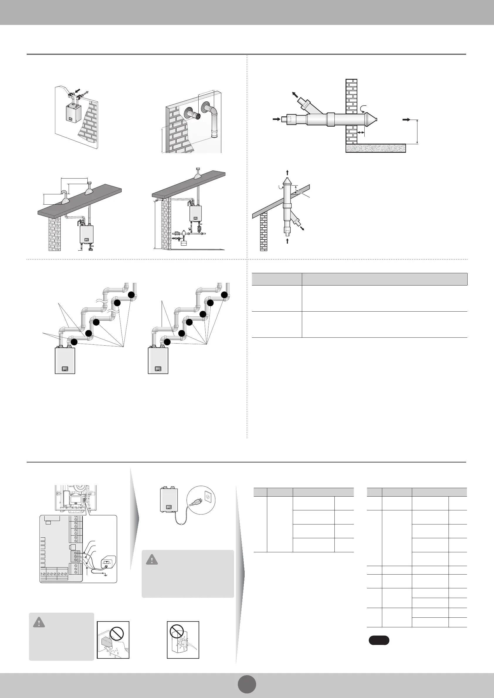
External LWCO Connection
(if required by local codes)
Power Connection
NULTI SW
T/S DHW
3.LWCO
2.AC24VL
1.AC24VN
FLOW SW LP SW
SYSTEM
SUPPLY
C
R W
C
R W
C
R W
C
LWCO
LINE
LINE
Neutral
Refer to your local codes to determine if an
LWCO device is required for your system and
ensure that the built-in device meets the
requirements.
120 V AC 60 Hz
Min. 2 Amp current with proper
grounding
CAUTION
Using abnormally high or low AC
voltage may cause abnormal operation,
thereby causing re which reduces the
life expectancy of this product.
CAUTION
Disconnect the power to
the boiler before installing
any wire connections on
the main PCB.
Safety
DO NOT touch
the power
cord with wet
hands.
DO NOT allow
the boiler to be
exposed to
excessive
amounts of
water.
Conrmation of DIP Switch Settings
DIP Switch 1 (6 switch unit) DIP Switch 2 (8 switch unit)
SW Function Setting
1 & 2
Operation
Status
Normal Operation
1-OFF,
2-OFF
2Step MAX
1-ON,
2-OFF
1Step MIN
1-OFF,
2-ON
1Step MAX
1-ON,
2-ON
SW Function Setting
1 Gas Type
Natural Gas
Propane Gas
1-OFF
1-ON
2 & 3
High
Altitude
0-1,999 ft
(0-609 m)
2-OFF,
3-OFF
2,000-5,399 ft
(610-1,645 m)
2-ON,
3-OFF
5,400-7,699 ft
(1,646-2,346 m)
2-OFF,
3-ON
7,700-10,100 ft
(2,347-3,078 m)
2-ON,
3-ON
4 Reserved - -
5 & 6 Country US/Canada
5-OFF,
6-OFF
7
Space
Heating
Thermostat
Used 7-OFF
Unused 7-ON
8
Exhaust
Temperature
Control
Used 8-OFF
Unused 8-ON
Note
When PCB DIP switch 2 #8 is set to
On, ensure that CPVC, polypropylene,
or stainless steel is used for exhaust
venting.
 Loading...