12
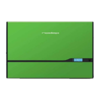
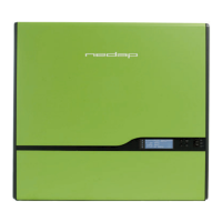
Figure 12: 1-phase sensor Figure 13: Connecting the 1-phase sensor
The cable on the sensor is terminated with an RJ45 plug, which must be inserted into the PowerRouter’s CAN
terminal. The sensor must be connected to the lower RJ45 socket, which is covered by a blind hole cover (see
Figure 13). Remove the blind hole cover and insert the RJ45 plug in the socket. The standard cable length is 1
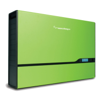
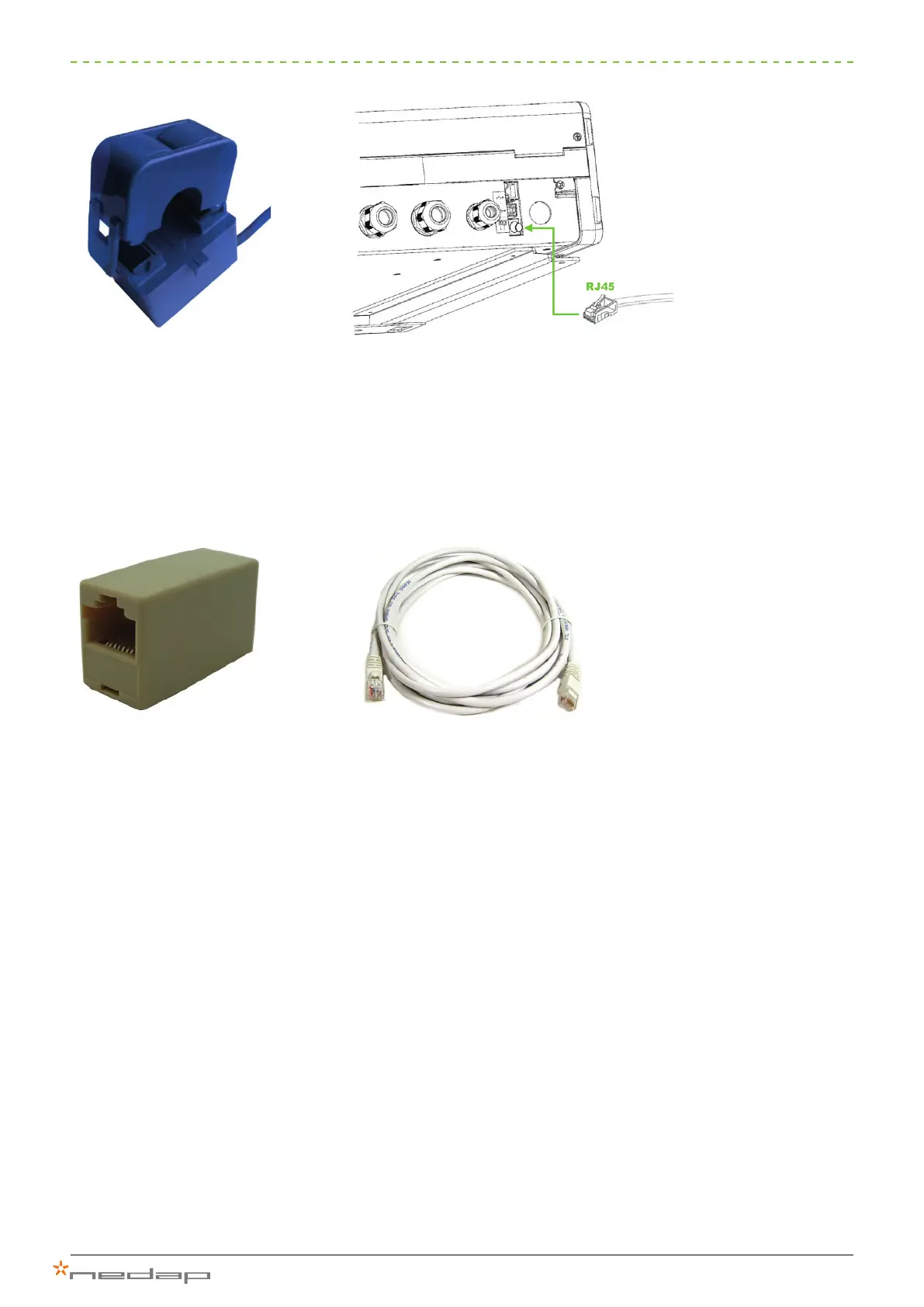
metre, but it can be extended with a CAT-5e cable having a maximum length of 10 metres by means of a CAT-
5e cable coupling.
Figure 14: CAT-5e coupling Figure 15: CAT-5e cable
Important information about the 3-phase grid connection
When a 3-phase grid connection is available the sensor must be connected to the same external conductor to
which the PowerRouter is connected. During initialisation of the system, sensor operation is tested to ensure
that the system is connected correctly. If the current sensor is not connected correctly, code P105H will appear
on the display.
 Loading...