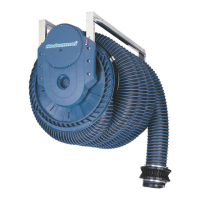
Exhaust Hose Reel 865
5Directions for use
WARNING!Risk of personal injury
• Check that there is enough suction in the
exhaust hose before it is connected to the
vehicle’s exhaust pipe. If not, check the fan’s
rotation direction and/or damper function.
If necessary check the installation of the fan
start switch.
• An exhaust gas detector is recommended.
5.1Operating the hose and fan
Aim the hand control towards the indicator of the
hose reel. The hand control will only operate the
one reel that has been correspondingly coded (re-
mote-controlled reel only). Stand by / power on is in-
dicated by flashing green light.
Downwards movement
1 Press the down-button shortly: The fan starts at
the upper limit for the hose. The started fan is in-
dicated by a fixed green light.
2 Press and hold the down-button: The hose moves
downwards which is indicated by a fixed red light.
Release the button when the required hose length
has been coiled out.
Upwards movement
• Push and hold the up-button: The hose moves up-
wards which is indicated by a fixed red light. Release
the button at the required upper hose position. The
fan stops.
5.2Indicator signals
See Figure7.
A Red light: Limit positions for the hose should be
set.
B Red light: The hose moves downwards or up-
wards.
C Green light: The fan is in operation.
D Green light: Stand by. Power on.
6Maintenance
WARNING!Risk of personal injury
Use a dust filter mask during service and re-
pair work inside the system (for example hose/
nozzle).
Check the following points at least once a year. Take
action when necessary.
• Check that Exhaust Hose Reel 865 is secured in the
ceiling or on the wall.
• Check the duct connections for leakage.
• Check the hose for damage.
• Check the coiling function of the hose. Setting the
limit positions for the hose.
• Check the hose connection in the connection piece
inside the drum.
• Check that there is enough suction capacity in
the extraction unit before it is connected to the
vehicle’s exhaust pipe. If not, check the fan impeller
rotation direction and/or damper function. If neces-
sary check the installation of the fan start switch.
7Spare Parts
CAUTION!Risk of equipment damage
Use only N$e$d$e$r$m$a$n$ original spare parts and ac-
cessories.
Contact your nearest authorized distributor or
N$e$d$e$r$m$a$n$ for advice on technical service or
if you require help with spare parts. See also
w$w$w$.$n$e$d$e$r$m$a$n$.$c$o$m$.
7.1Ordering spare parts
When ordering spare parts always state the following:
• The part number and control number (see the
product identification plate).
• Detail number and name of the spare part (see
w$w$w$.$n$e$d$e$r$m$a$n$.$c$o$m$/$e$n$/$s$e$r$v$i$c$e$/$s$p$a$r$e$-$p$a$r$t$-
$s$e$a$r$c$h$).
• Quantity of the parts required.
8Recycling
The product has been designed for component mater-
ials to be recycled. Different material types must be
handled according to relevant local regulations. Con-
tact the distributor or$N$e$d$e$r$m$a$n$ if uncertainties arise
when scrapping the product at the end of its service
life.
EN
15


 To Next Page
 Loading...

