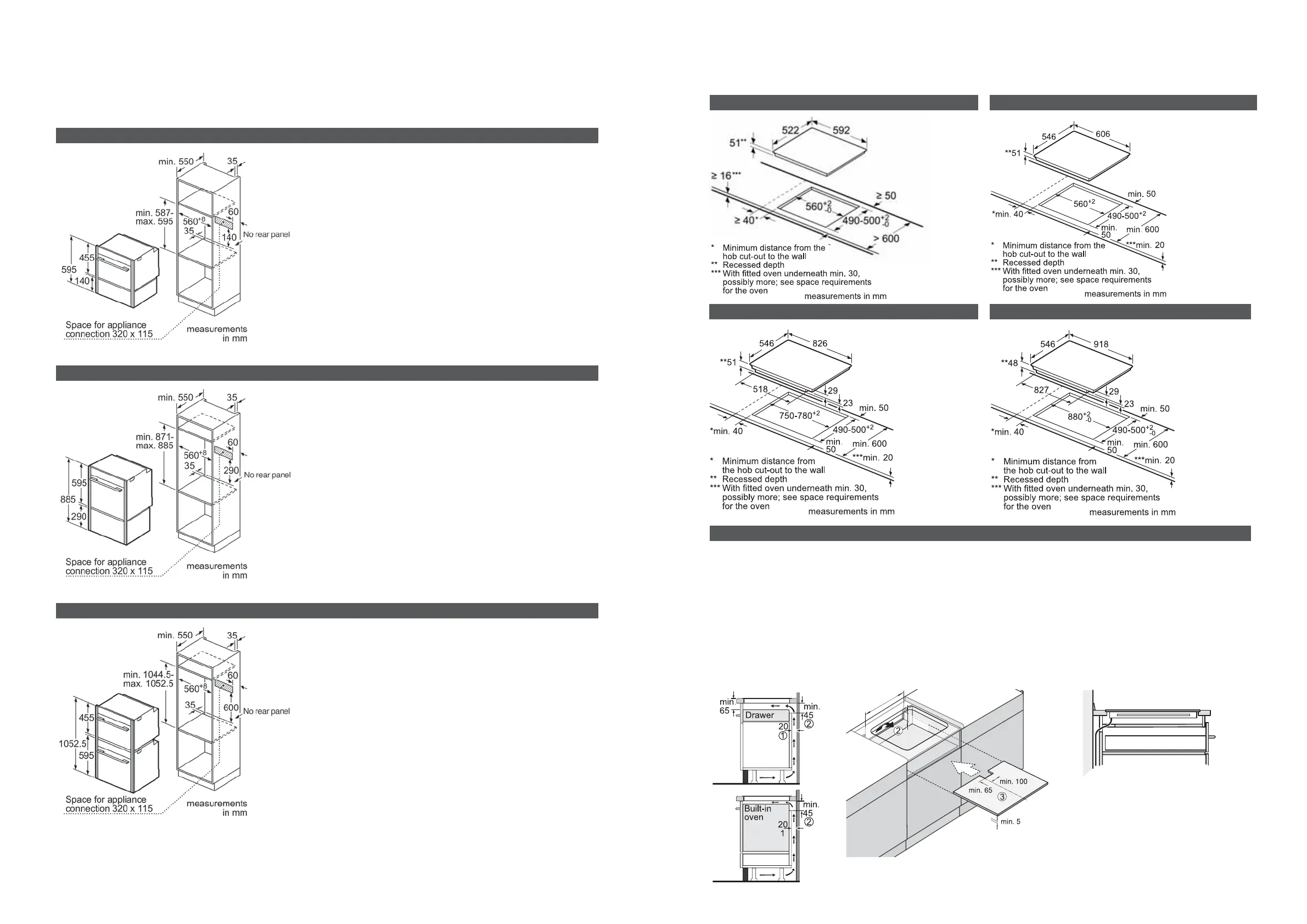
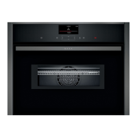
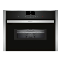
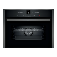
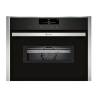
SPECIFICATION DIAGRAMS – SEAMLESS COMBINATION KITS
*
&0&203$&7$33/,$1&(&0:$50,1*'5$:(5²=6=;
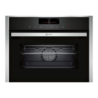
The built-in solution from NEFF for vertical installation is SeamlessCombination. Stainless steel side panels now make it possible to turn
two appliances installed on top of each other into a single unit, without the need for an intermediate shelf.
Additional SeamlessCombination accessories:
=6=;²6HDPOHVV&RPELQDWLRQLQVHUWLRQÁRRUWRFRPELQHFPIXOOVL]HRYHQFPFRPSDFWDSSOLDQFH
*The SeamlessCombination Kits are not applicable with the C17KS61H0.
&0)8//6,=(29(1&0:$50,1*'5$:(5²=6=;
&0)8//6,=(29(1&0&203$&7$33/,$1&(²=6=;
All descriptions and technical diagrams are intended as a guide only. For additional technical information, full dimensional and installation
details, please refer to the instruction and installation manuals supplied with the appliance, which can be accessed on-line for your
SODQQLQJSXUSRVHVYLDZZZQHɡFRQ]$OOPHDVXUHPHQWVDUHLQPP
,1'8&7,21&22.723,167$//$7,21127(6
,QGXFWLRQFRRNWRSVKDYHDFRROLQJIDQWRSURWHFWWKHDSSOLDQFH·VHOHFWURQLFVIURPRYHUKHDWLQJ,QWKHFDVHRILQVXIÀFLHQWDLUFLUFXODWLRQ
in the cabinet the appliance’s output will be reduced to prevent electronic damage.
9HQWLODWLRQJDSRIPPPXVWEHSUHVHQWEHWZHHQFDELQHWEDFNZDOODQGÀQLVKHGZDOO
2. Intake through the cabinet’s back wall. In the cabinet’s back wall plan a recess of at least 45mm in height from the worktop's bottom
edge. The minimum width is 550mm for a 60cm to 70cm induction cooktop. 820mm for a 90cm cooktop.
$OOLQGXFWLRQFRRNWRSVPXVWKDYHDQLQWHUPHGLDWHÁRRULQVWDOOHGEHQHDWKFRYHULQJWKHIXOOZLGWKRIFRRNWRS,IDQRYHQFRPSDFW
DSSOLDQFHLVLQVWDOOHGGLUHFWO\EHQHDWKDQLQGXFWLRQFRRNWRSQRLQWHUPHGLDWHÁRRULVUHTXLUHGSURYLGLQJWKHRYHQFRPSDFWDSSOLDQFH
restricts access to the entire underside of the cooktop.
If the cooktop is installed over a compact oven, there must be a distance of 60mm between the top of the oven and the top of a working
surface. If the interior width of the kitchen unit is less than 880mm, a cut must be made in the side walls.
Note: All induction cooktops can only be wired to main switchboard. The electrical connection should only be made in accordance with
the regulations of the national authorities.
min. 550/820
min. 45
SPECIFICATION DIAGRAMS – INDUCTION COOKTOPS
&0,1'8&7,21&22.723²7)'; &0(;7(1'(')/(;,1'8&7,21&22.723²7761
&0)/(;,1'8&7,21&22.723²7761
&0(;7(1'(')/(;,1'8&7,21&22.723²7761
All descriptions and technical diagrams are intended as a guide only. For additional technical information, full dimensional and installation
details, please refer to the instruction and installation manuals supplied with the appliance, which can be accessed on-line for your
SODQQLQJSXUSRVHVYLDZZZQHɡFRQ]$OOPHDVXUHPHQWVDUHLQPP
QHɡFRQ] QHɡFRQ]



 To Next Page