5. DMX CONNECTION AND DMX PROTOCOL
The device is controlled by universal DMX 512 pro-
tocol, DMX address is the start channel used to re-
ceive instructions from the external controller. For
independent control, each xture must be assigned
its unique address control channels. For example,
this device has four channel modes: 11/14, if we set
the mode at standard 11 channels mode, and there
are several models need to be independently con-
trolled, we just simply address rst xture at 1, and
second xture at 12, third one at 33, etc.
If the devices have the same address, they will be-
have synchronically.
DMX addressing is limited, don’t set the address so
high that without enough control channels for the
xtures.
Display is ashing when no DMX signal is received.
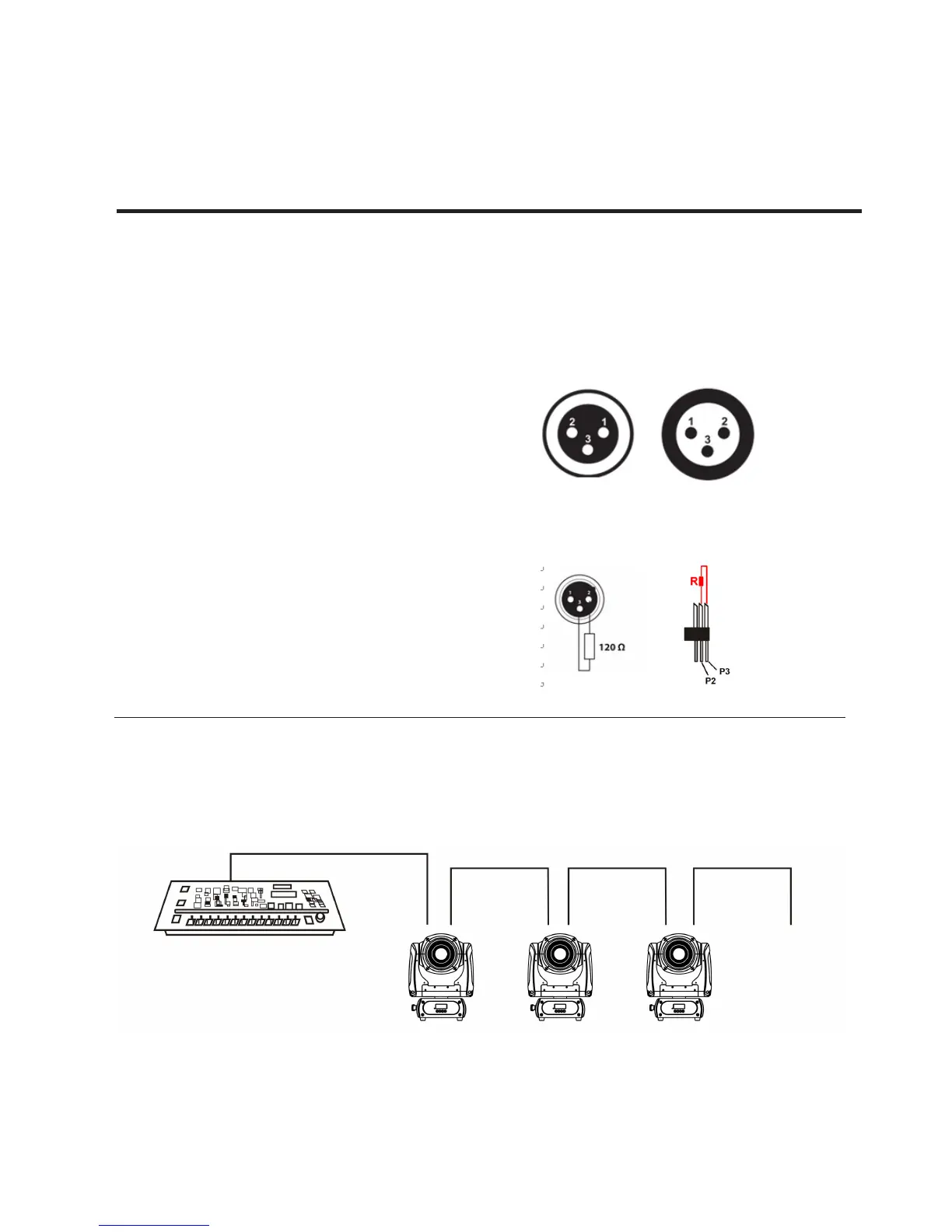
This device is equipped with 3-pins DMX in and
out sockets only. Pin 1 = GND, Pin 2 = Signal (-)
, Pin 3 = Signal (+)
The termination is prepared by soldering a 120Ω
resistor between pins 2 and 3.
DMX addressing
Connection: use DMX cable with 3-pin XLR-plugs
to connect the controller with the xture or one
xture with another.
English version
 Loading...