Step Perform on each controller
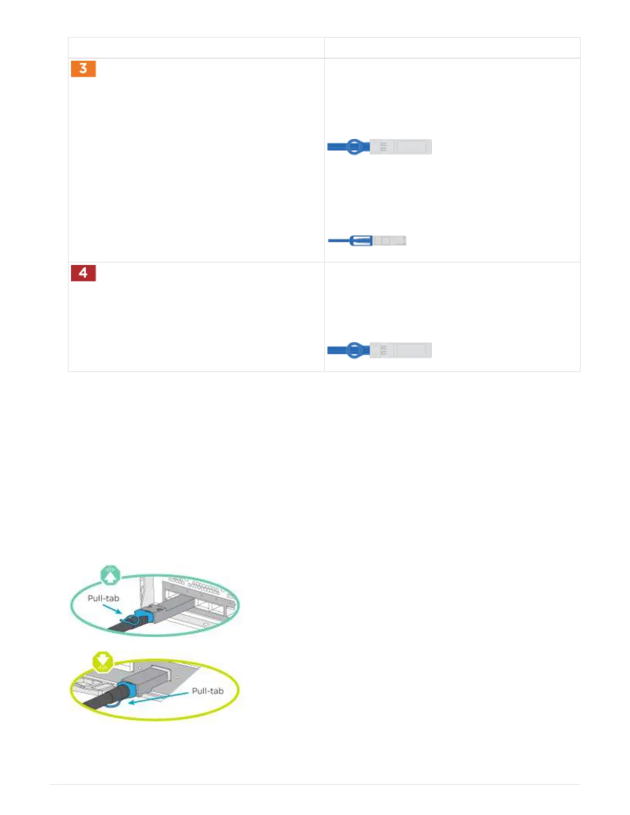
Cable 25GbE network switches:
Ports in slot A3 and B3 (e3a and e3c) and slot A9
and B9 (e9a and e9c) to the 25 GbE network
switches.
40GbE host network switches:
Cable host‐side b ports in slot A4 and B4 (e4b) and
slot A8 and B8 (e8b) to the host switch.
Cable 32 Gb FC connecions:
Cable ports in slot A5 and B5 (5a, 5b, 5c, and 5d)
and slot A7 and B7 (7a, 7b, 7c, and 7d) to the 32
Gb FC network switches.
2. To cable your storage, see Step 4: Cable controllers to drive shelves.
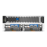
Step 4: Cable controllers to drive shelves
Option 1: Cable the controllers to a single NS224 drive shelf in AFF A900
You must cable each controller to the NSM modules on the NS224 drive shelf on an AFF
A900 system.
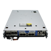
Before you begin
• Be sure to check the illustration arrow for the proper cable connector pull-tab orientation. The cable pull-tab
for the storage modules are up, while the pull tabs on the shelves are down.
8