Step Perform on each controller
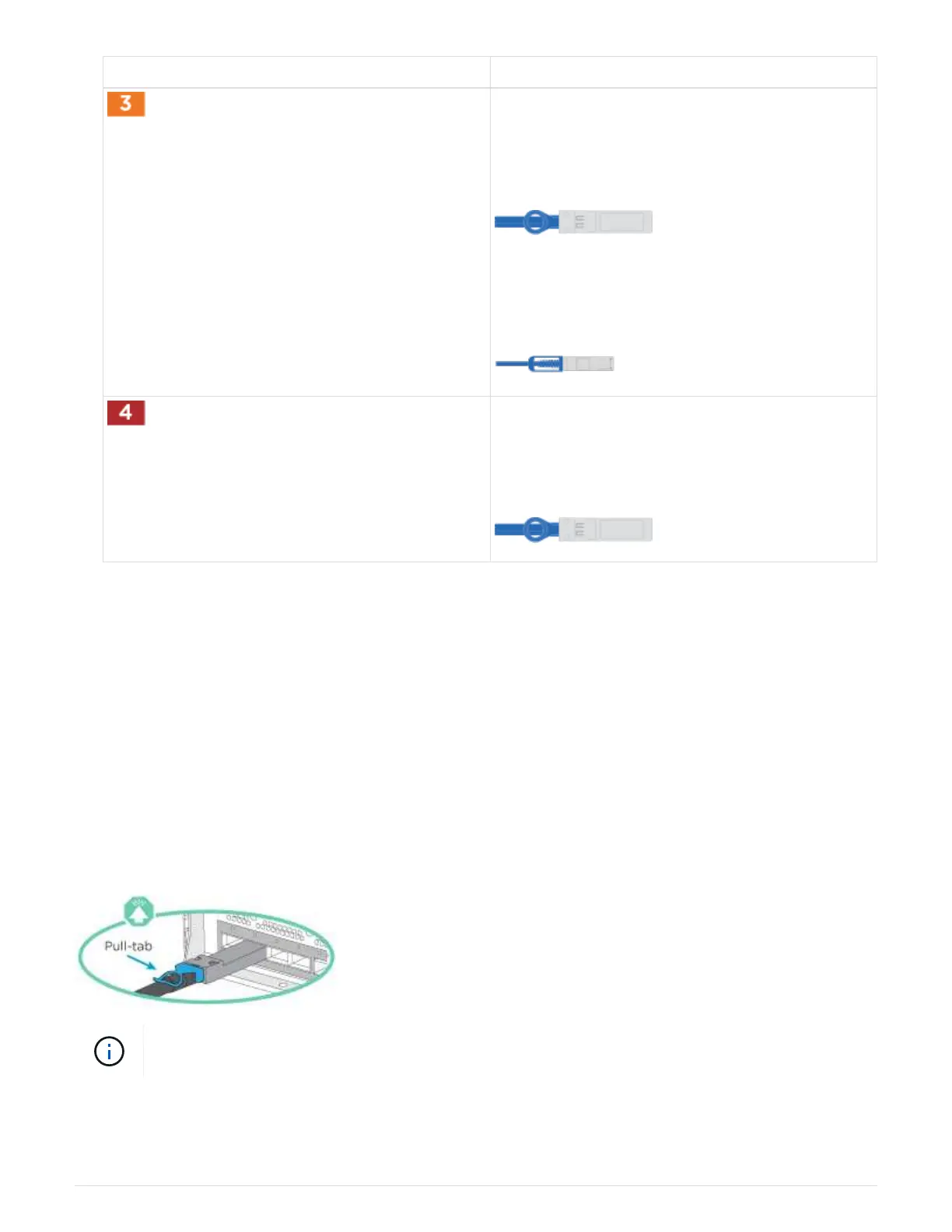
Cable 25 GbE network switches:
Ports in slot A3 and B3 (e3a and e3c) and slot A9
and B9 (e9a and e9c) to the 25 GbE network
switches.
40GbE host network switches:
Cable host‐side b ports in slot A4 and B4 (e4b) and
slot A8 and B8 (e8b) to the host switch.
Cable 32 Gb FC connections:
Cable ports in slot A5 and B5 (5a, 5b, 5c, and 5d)
and slot A7 and B7 (7a, 7b, 7c, and 7d) to the 32
Gb FC network switches.
2. To cable your storage, see Step 4: Cable controllers to drive shelves.
Option 2: Switched cluster
Management network, data network, and management ports on the controllers are
connected to switches. The cluster interconnect and HA ports are cabled on to the
cluster/HA switch.
Before you begin
You must have contacted your network administrator for information about connecting the system to the
switches.
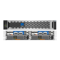
Be sure to check the direction of the cable pull-tabs when inserting the cables in the ports. Cable pull-tabs are
up for all networking module ports.
As you insert the connector, you should feel it click into place; if you do not feel it click, remove
it, turn it around and try again.
1. Use the animation or illustration to complete the cabling between the controllers and to the switches:
Animation—Cabling a switched cluster
6