b. Guide the riser along the pins in the controller module, and then lower the riser into the controller
module.
c. Swing the locking latch down and click it into the locked position.
When locked, the locking latch is flush with the top of the riser and the riser sits squarely in the
controller module.
d. Reinsert any SFP modules that were removed from the PCIe cards.
Step 4: Reinstall the controller module
After you replace a component within the controller module, you must reinstall the controller module in the
system chassis and boot it.
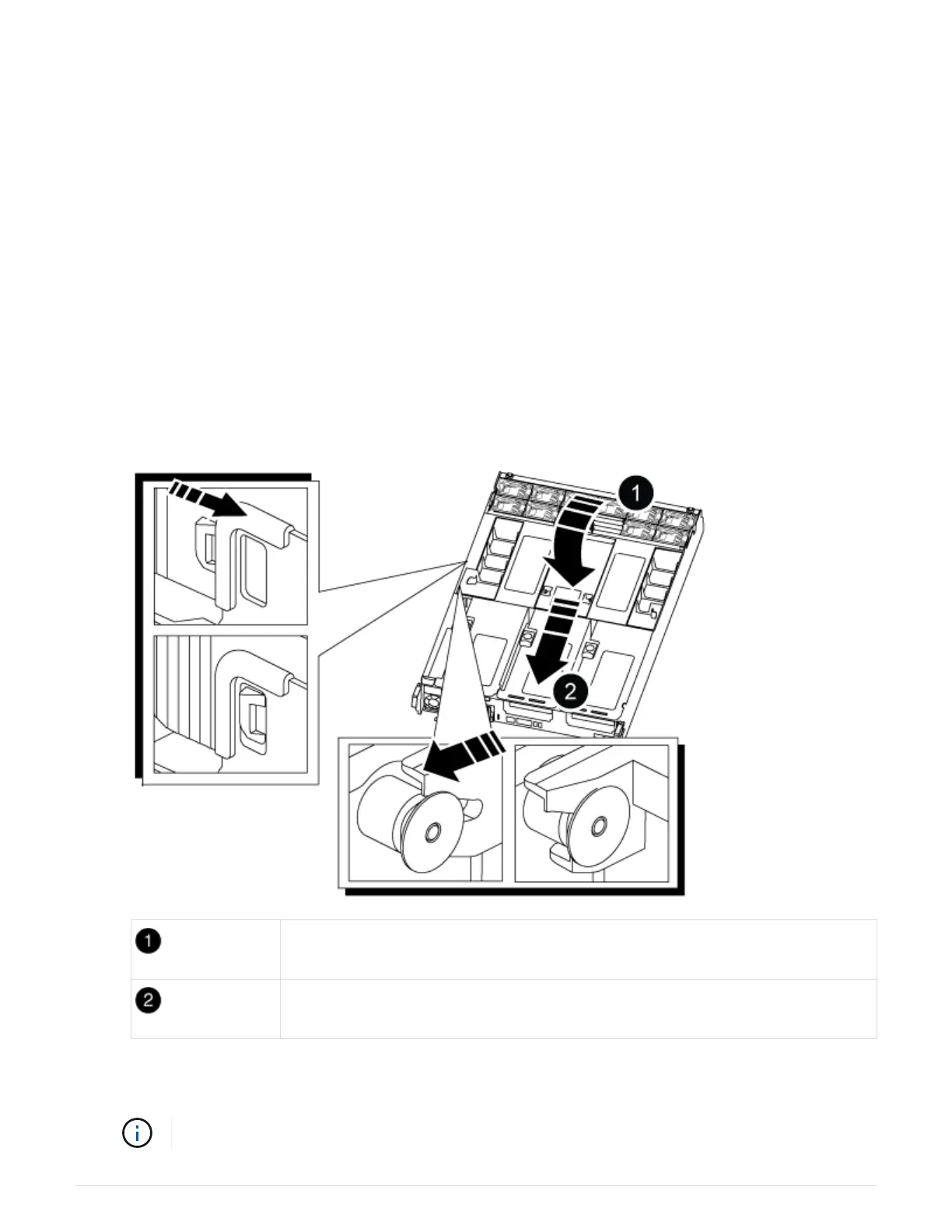
1. If you have not already done so, close the air duct:
a. Swing the air duct all the way down to the controller module.
b. Slide the air duct toward the risers until the locking tabs click into place.
c. Inspect the air duct to make sure that it is properly seated and locked into place.
Locking tabs
Slide plunger
2. Align the end of the controller module with the opening in the chassis, and then gently push the controller
module halfway into the system.
Do not completely insert the controller module in the chassis until instructed to do so.
1028